
- Home
- Companies
- Acme Engineering Prod. Ltd.
- Articles
- Automatic Scraper Strainers for ...
Automatic Scraper Strainers for Wastewater Treatment
Advanced strainers are designed to offer far greater reliability than conventional options under unpredictable conditions. An industry expert provides insight into strainer use, design, selection, installation and construction. Plants in the chemical process industries (CPI) have long relied on strainers to filter liquids and slurries of particles and impurities, as well as to protect downstream equipment, such as pumps, valves and heat exchangers, from damage duo to debris and other contaminants. As such, they play a vital role in the manufacturing of products such as acids, alkalis, fertilizers, inks, paints, coatings, soaps, detergents, toiletries, perfumes, explosives, glues and essential oils. Strainers also play a critical role in the wastewater treatment systems used in chemical processing. Often placed after clarifiers that settle suspended solids from liquids, strainers can remove contaminants of many different sizes, from small organic material to large debris prior to additional processing. This helps to reduce maintenance and facilitate compliance with regulations such as those contained in U.S. Environmental Protection Agency Clean Water Act.
Cooling water brought in from nearby oceans, lakes or rivers must also bo strained to remove detritus and particulate matter. Process cooling-tower water in open and closed-loop systems is also filtered to remove scale, grit, fine sand and biological matter.
With so many possible applications, many chemical processors are now turning to self-cleaning systems. Advanced automatic scraper strainers can filter out both large and small particles, as well as adjust to unpredictable conditions, such as varying pressure, particle size, solids load and even the presence of sticky biological materials.
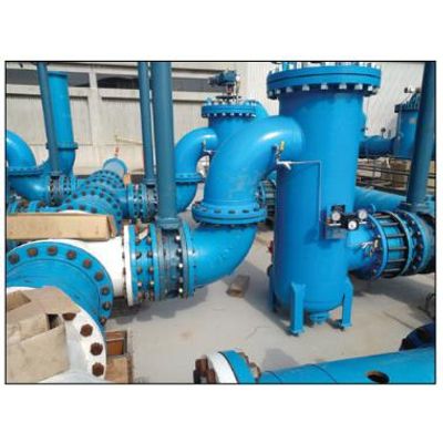
These more automated systems essentially eliminate manual handling and maintenance, including the need to open and dump debris and contaminants (Figure 1).
Designed for variability
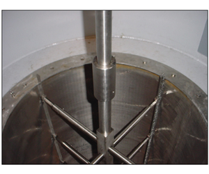
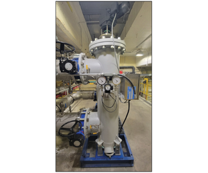
Today, automatic scraper strainers are designed to tolerate "surprises," while also meeting various process, cooling and water treatment requirements. As an example, advanced units are designed to remove both very large and very small suspended solids. This is accomplished by a spring-loaded blade and brush system, managed by a fully automatic control system. Tour scraper brushes rotate at 8 rpm, resulting in a cleaning rate of 32 strokes per minute. The scraper brushes insert into wedge-wire slots and dislodge resistant particulates and solids. This approach enables the scraper strainers to resist clogging and foul ing when faced with large solids and high solids concentration. It ensures a complete cleaning and is very effective against organic matter "biofoul-ing" (Figure 2).
To protect sensitive membranes, process cooling equipment, and wastewater treatment systems downstream of the clarifiers, ?00-um automatic scraper strainers can be used to filter up to 6,000 gal/ min of the water and spillover. After washdowns, the technology can effectively capture even sticky biological substances, like algae, and other contaminants that are washed loose. This can protect additional downstream processes, such as membrane filtration or ozone-disinfection equipment, which could be utilized it further purification or inactivation of pathogenic organisms is required.
An advantage of automatic scraper strainers is that the technology does not require continuous water pres sure to keep the screen clean. Unlike backwash strainers, scraper strainers do not rely on a pressurized backwash to remove solids from the screen. Instead, a blade and brushes provide more reliable cleaning under varying conditions
The blade and brushes scrape the screen clean, and the small brush filaments get into the slots. So, if a solid is stuck in a slot between the wedge wire, the filaments will push the solid through (Figure 3).
Scraper strainers allow the solids to accumulate at the bottom of the vessel, where the blowdown valve will open periodically to clear them out. Since a gate valve isolates the solids collection area, the wastewater flow continues in the regular section of the strainer.
Blowdown occurs only at the end of the intermittent scraping cycle when a valve is opened for a few seconds to remove solids from the collector area. Liquid loss is well below 1 % of the total flow.
The blowdown can operate without moving parts and can even perform from the suction side of a pump. These capabilities, which are not possible for a backwash unit, aid design flexibility and can facilitate installation at space-constrained plants.
Unlike a manual strainer, it is not necessary to open and clean an automatic scraper strainer. No one needs to manually blow down the solids. Since the operation of the scraper strainer is automatic, it is es sentially a "set-and-forget" type of system that lets operators walk away and focus on other aspects of the facility, which helps to reduce overall labor costs.
Strainer selection Selecting an automatic scraper strainer for chemical processing, cooling or wastewater treatment involves assessing various factors. Initially, the flowrate capability of the strainer, which is closely linked to viscosity, should be considered.
Evaluating the fluid`s How and vis cosity guides the selection of an appropriate pipeline size. If a slower flow is preferred by the chemical processor, opting for larger piping might be necessary. When dealing with high-viscosity fluids, choosing a larger pipe diameter can facilitate smoother fluid movement. Introducing heat to reduce viscosity could also be recommended, particularly in petrochemical applications, such as bunker fuel, where optimal flow occurs at higher temperatures.
Regardless of the fluid type, the analysis extends to the content being transported, including the size and concentration of solids present in the flow.
When the fluid exhibits high viscosity and contains a significant solids concentration, it is generally necessary to use a larger strainer for situations where the processor opts against altering the pipeline dimensions. I he strainer should be oversized to handle the anticipated high solids content. As the flow progresses through the pipeline, the solids remain suspended within the flow, potentially increasing the weight of the media, but not necessarily impeding its movement.
An alternative approach involves elevating the pump pressure to sustain the desired tlowrate. Upon reaching the filtration screen of the strainer (a porous barrier), smaller solids are likely to pass through while larger particles are retained.
The subsequent consideration revolves around determining the neeessary surface area for tho filtration screen, contingent upon the desired level of filter fineness. Coarse filtration primarily targets the removal of larger particles, such as 0.5, 0.25 or even 0.125 in. Because the aperture size in the filtration screen is of substantial dimensions, its impact on pressure drop is minimal.
Nonetheless, as the strainer filtration size progresses toward finer specifications below 300 um, such as 250 or 200 pm, the chemical processor must contemplate enlarging the screen`s dimensions to counter a notable pressure drop.
Upon the initial selection of the strainer size, subsequent adjustments to the screen`s dimensions will be made based on the specific constituents requiring extraction from the fluid, while maintaining an acceptable level of system pressure drop.
When a strainer is being selected, it is crucial for the processor to provide sufficient information to ensure the correct choice for the application. Providing a flowrate, solids loading and desired filtration level is generally satisfactory. However, having comprehensive information about the entire system allows for a more informed decision-making pro-cess. Potential issues downstream from the desired strainer location can bo identified by examining the piping and instrumentation diagram (I`&ID) for the process.
For instance, if 500-um straining is required, but subsequent membrane filters demand 100-um filtration, there is a conflict. I his poses a challenge in addressing the filtration requirements. Transparency is key. Sharing information with the filter manufacturer enhances the success of the process. If confidentiality is a concern for the chemical processor, a nondisclosure agreement can be signed to safeguard intellectual property contained in the P&ID.
Strainer location
In challenging industrial applications, chemical processors must make a critical decision regarding the positioning of the strainer in relation to the pump. For highly viscous fluids, positioning the strainer after the pump is recommended. This typically requires a specialized pump, like a sludge pump or a positive displacement pump, that pulsates the solids. An alternative approach involves utilizing a combination system with a macerator placed before the pump to reduce the solids size for optimal strainer performance. The macerator operates effectively without requiring pressure.
There are certain instances whore the strainer is positioned before the pump. Ideally, a positive-pressure system is preferred over a vacuum setup. However, appropriate measures can be taken to ad dress vacuum conditions. One design solution involves incorporating a collector at the bottom, flanked by gate valves that facilitate isolation of collected solids for discharge. This design allows for effective operation even in the presence of minimal vacuum, be cause the collector can be isolated during discharge.
Alternatively, a small pump on the blowdown line can be utilized to extract solids from the strainer. This method has been successfully implemented in scenarios with limited positive pressure, typically in the range of 1-? psi, and where transportation of blowdown material was required over significant distances. In such cases, relying solely on low pressure is insufficient, necessitating the use of a secondary trash pump to facilitate solid movement.
Materials of construction
In corrosive chemical processing settings, the utilization of stainless-steel construction instead of coat ings on small 1- to 6-in. straining systems could be a more economical and appealing option. Coating involves a consistent time investment regardless of unit size, leading to disproportionate costs associated with smaller units.
For larger units, the implementation of a lining may offer a more cost-effective solution. An example includes a scenario where a 48-in. carbon-steel vessel with a 30-in. connection required a corrosive application that was lined with duplex stainless steel, featuring a chromium con tent of up to 22%. In this setup, the components in contact with water were constructed of duplex stainless stool, while tho pressure vessel itself remained carbon steel, representing a cost-effective approach.
However, chemical processes can be highly corrosive to the strainers used. Typical strainers constructed of carbon steel or even stainless steel can quickly deteriorate when exposed to corrosive chemical fluids for extended periods. For this reason, costly duplex stainless steel and super duplex stainless steel (with chromium content up to 25%) are often utilized for greater corrosion resistance. However, even with the added expense, virtually continuous exposure to chemical laden fluids can still lead to corrosion issues.
In most applications with an oil-based solution, the material of construction of the strainer is decided based on the piping. II all the piping is carbon steel, a stainless-steel strainer is probably not needed. The internals are going to be made from stainless steel. The pressure vessel can be carbon steel, but processors may find that fiber-reinforced plastic (FRP) is preferable as a pressure vessel for their automatic strainers.
In fact, CPI facilities can save approximately half the cost or more when the strainer`s intake vessels and piping are built with FRP, while only the internals are constructed with super duplex stainless steel.
FRP is a composite material made up of polymer supported with fibers for added strength. FRP is already widely utilized for the piping used to carry corrosive seawater for once-through process cooling at power plants. Due to the FRP`s strength, the material can also be used to build to the standards of the American Society of Mechanical Tngineers {ASML) Boiler and Pressure Vessel Code (BPVC) Section X, which establishes requirements for the fabrication of FRP pressure vessels.
As a much more cost-cffcctivc alternative, seek out an original equipment manufacturer (OEM) that offers the option of using exceptionally corrosion-resistant FRP for external strainer construction, including the pressure vessel itself. The internal mechanism is still manufactured with super duplex or similar steels.
There is no need to fear utilizing FRP for pressure vessels. FRP was initially employed for pressure vessels in 2007. and it continues to operate effectively. FRP has also been used for high-pressure applications reaching 300 psi (20 bars).
In the context of chemical process cooling, it is advisable to employ FRP for all piping within seawater intake systems due to its cost-effectiveness and the corrosive nature of seawater.
Since FRP is far more corrosion-resistant to chemical processes than carbon steel or stainless steel, yet costs just a fraction of expensive duplex or super duplex stainless steels, it is becoming a popular construction material for chemical process straining equipment.
Chemical process, cooling and wastewater-treatment conditions can change along with production schedules and the seasons, so it is important for companies to utilize technology that can flexibly and reliably meet compliance requirements and protect downstream equipment.
Automatic scraper strainers are designed to do so and can tolerate the inevitable surprises and variability, while also helping to minimize maintenance. Chemical processors that consult with an expert on automatic scraper strainer selection will benefit from greater process reliability and quality, as well as equipment longevity, at an economical cost.