
Airfield Systems, LLC
AirDrain for Green Roofing
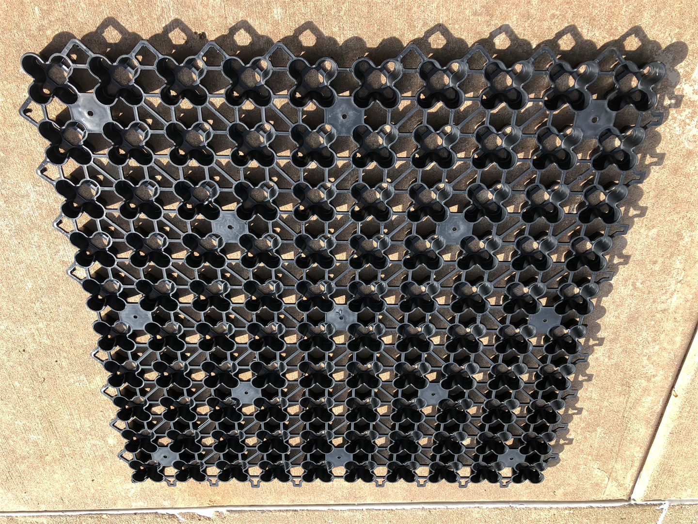
THE ADVANCED GEOCELL FOR ROOFTOP SPORTS FIELD CONSTRUCTIONRAPID DRAINAGE, COLLECTION, RETENTION AND REUSE FOR NATURAL AND ARTIFICIAL TURFAirDrainby AirField SystemsSUSTAINABLEDESIGNwithAirDrain – What drains better than Air? Green Roofing - Synthetic or Natural Turf With limited space on campus, high schools and colleges are turning to rooftop sports surfaces to create multi-use green areas. Building a rooftop sports ?eld with an AirField System provides drainage under 100% of the playing surface, prevents ponding, and moves water ef?ciently for reuse elsewhere on campus. Over 1,000,000 square feet of AirDrain rooftop drainage system installed and counting. Natural Turf- Chesapeake Energy 74,000 sqft. Synthetic Turf- Escuela Campo Alegre 76,000 sqft. and WPI “Worcester Polytechnics Institute” 174,000 sqft. Benefits of AirField in a green roofing system include: ? AirDrain creates and helps maintain a more consistent Gmax for Synthetic Turf ? ASTM testing proves AirDrain’s shock absorption properties reducing strain on joints and ligaments ? AirDrain can be reused when the Synthetic Turf must be replaced ? Can help qualify for LEED™ and other green building credits ? A smaller carbon and development footprint with reduced site disturbance ? Water harvesting reclamation and reuse is easy ? AirDrain creates a one inch air barrier on the rooftop increasing the insulating properties. ? AirDrain is a 100% recycled copolymer with the impact modifier “metallocene” qualifying it as a “No Break” plastic. Making it able to withstand extreme heat and cold and still maintain performance. ? Resins can be made to the following specification “Flammability UL 94, Flame Retardant, High Impact Polypropylene Copolymer Resins” Synthetic Turf 1” AirDrain System provides .576 gallons per sqft. of water storage or open space capacity for rapid drainage preventing surface ponding Geotextile Fabric Waterproof Sealed Roof per Architect/Engineer Geotextile Fabric ASTM Testing Proves the AirDrain Synthetic Turf Drainage Doubles as a Drainage Layer and Shock Pad Whether installed on an aggregate base, concrete or asphalt the AirDrain drainage grid helps provide you with a consistent GMAX (as seen below) across the entire field. Some factors that might influence a change in GMAX would be an inconsistency of the infill or wear of the synthetic turf fibers. Unlike traditional shock pads / e-layer the AirDrain is 1" high, has a 92% air void. This unmatched vertical and lateral drainage all but eliminates standing water. Some of the Benefits of an AirField Synthetic Turf Drainage System include: • AirDrain creates and helps maintain a constant Gmax for artificial turf (See below) • Shock absorption reduces the strain on joints and ligaments • AirDrain is only limited by the drainage capacity of the profile above it and the exit drain • AirDrain can be reused when the synthetic turf must be replaced • Can help qualify for LEED and other green building credits • A smaller carbon and development footprint with reduced site disturbance • Water harvesting reclamation and reuse is possible • AirDrain is a 100% recycled copolymer with the impact modifier metallocene qualifying it as a “No Break” plastic *** AirDrain can be made to the following specification “Flammability UL 94, 30% Fiberglass Reinforced, High Impact, Flame Retardant Polypropylene Copolymer Resins” for Rooftop applications. FLAMMABILITY @ 0.100 in V-0/5VA* UL94* GMAX Results for: Turf - 2 1/2” Slit Film, in filled with 50% Green Rubber Infill and 50% Silica Sand. The drainage/shock pad and turf underlying substrate consists of a concrete deck/rooftop, coated with a waterproof membrane and 2 separate layers of 5 ounce 100% recycled polyester geo-textile filter fabric. The Standard Test Method for Shock-Absorbing Properties of Playing Surface Systems and Materials (ASTM F1936-98 American Football Field) testing locations and procedure were preformed. The tests were performed using a Triax 2000 A-1 Missile, tripod mounted Gmax registration unit (www.triax2000.com). This report presents background information on the test procedures, existing conditions, test results and observations DETAIL ASCALE .75:1A11223344A AB BC CD DSHEET 1 OF 1 DRAWNCHECKEDQAMFGAPPROVEDGary 9/22/2012DWG NORooftop_Assembly_SYN_ RT_001TITLESIZECSCALEREVThe information contained in this drawing is the sole property of Airfield Systems. Any reproduction in part or as a whole without prior written consent is prohibited.Airfield SystemsThis drawing, specifications and the information contained herein is for general presentation purposes only. All final drawings and layouts should be determined by a licensed engineer(s).Synthetic TurfGeotextileGeotextileImpermeable Liner*Rooftop Surface perArchitect/EngineeringSpecificationsAirDrain? GeogridSynthetic TurfRoof TopAirDrain? Sythetic TurfRooftop Drainage2Nailer Board*Impermiable Liner and or other waterproofing must be specified by a qualified engineer.Geotextile*AirField Systems, LLC8025 N May Ave, Suite 201Oklahoma City, OK 73120www.airfieldsystems.com(405) 359-3375 DETAIL ASCALE 0.75 : 1A11223344A AB BC CD DSHEET 1 OF 1 DRAWNCHECKEDQAMFGAPPROVEDGary 4/2/2012DWG NORooftop Assembly RT_004TITLESIZECSCALEREVThe information contained in this drawing is the sole property of Airfield Systems. Any reproduction in part or as a whole without prior written consent is prohibited.Airfield SystemsThis drawing, specifications and the information contained herein is for general presentation purposes only. All final drawings and layouts should be determined by a licensed engineer(s).Rooftop Surface per Architect/EngineeringSpecifications Impermeable Liner*AirDrain? GeogridGeotextileNatural TurfRoof Top Sand Root Zone MixAirdrain Natural TurfRooftop DrainageGeotextile6Geotextile*AirField Systems, LLC8025 N May Ave, Suite 201Oklahoma City, OK 73120www.airfieldsystems.com(405) 359-3375 *Impermiable Liner and or other waterproofing must be specified by a qualified engineer. AirField Systems Illustrated Manual for Green Roof System Sub-Surface Drainage 1. The roofing membrane underlying the proposed green roof area is to be verified as in compliance with all project specifications before work commencement on the AirField Sub-Surface Drainage System. Any discrepancies noted upon preliminary roofing inspection are to be satisfactorily repaired according to related specification sections and repairs verified before proceeding with work. 2. Once the roofing membrane system has been inspected and accepted, begin installation of the AirDrain™ GeoCell material over the approved roofing membrane system. The AirDrain™ GeoCell panels are to be installed with the larger diameter clover openings facing upwards. Place the first GeoCell panel to the roof area’s upper left hand corner. It is of primary importance to orient the GeoCell materials with the integral indicator tab to the panels bottom left hand corner (refer to Figures 17). Proper sequencing and orientation of panels will result in a rapid installation. The GeoCell panels are to be installed across the roofing membrane system in a rowed pattern. Staggering of rows will allow for multiple row completion by a multi-manned crew. Secure the first panel (1-1) and commence with panels 1-2, 1-3 and so on with one directional pull to secure (see Figures 16, 18 and 19). Once the first row has progressed across the field, start with the second row. By maintaining proper GeoCell panel orientation, the top edge panel connectors will drop into the previously installed panel receptors after the one directional pull secures the panel (see Figures 18). The GeoCell panels can be shaped to individual field areas as needed with an appropriate cutting device. 3. Install geo-textile filter fabric layer over the AirDrain™ GeoCell material. Firmly attach one end of the geo-textile filter fabric roll to the GeoCell panel edge with approved adhesive. Roll the geo-textile filter fabric across the entire width of the roof area until it reaches the GeoCell panel on the opposite side of the roof. Firmly attach the geo-textile filter fabric to the GeoCell panel edge on this side of the roof. Apply 2 to 4 inches of approved adhesive with a paint roller on top surface of fabric edge. Firmly attach the next geo-textile filter fabric roll to the GeoCell panel edge. Overlap the first piece of filter fabric by approximately 6 inches to cover the 2 to 4 inches of approved adhesive and roll out the next filter fabric section across the roof. When the opposite side of the roof is reached, firmly attach the filter fabric to the GeoCell panel outside edge. Repeat this process until all the AirDrain™ AirField Systems 1 Illustrated Manual for Green Roof System GeoCell is completely covered with geo-textile filter fabric. Once the geo-textile filter fabric installation is complete there should be no visible gaps, puckering, folds, wrinkles or excessive loose material overhangs. Installed geo-textile filter fabric is to be smoothly laid across all the AirDrain™ GeoCell material. 4. Once the geo-textile fabric has been installed atop the AirDrain™ GeoCell material, the Sub-Surface Drainage System is complete and ready for inspection and acceptance by the Green Roof System Contractor. Satisfactorily repair all deficiencies noted and obtain approval and acceptance before proceeding with green roof system installation. Minimize any required vehicular traffic on completed sub-surface drainage system. Where vehicular traffic is required, limit equipment to flotation tire type and minimize vehicle speed and turning on drainage system to the greatest extent possible. Any sub-surface drainage system damaged by green roof system installation is to be satisfactorily repaired and accepted before the green roof system is installed. Refer to AirDrain™ Rooftop Drainage for Synthetic Turf or Natural Turf drawings for typical completed green roof system cross section. DISCLAIMER: The following drawings and/or general installation instructions are provided only to show a concept design for installation and are not instructions for any particular installation. These drawings and general instructions are not complete and are provided only to assist a licensed Geo-Technical Engineer, a Landscape Architect and/or Civil Engineer in preparing actual construction and installation plans. These drawings and instructions must be reviewed by a licensed Geo-Technical Engineer, a Landscape Architect and/or Civil Engineer and adapted to the condition of a particular installation site and to comply with all state and local requirements for each installation site. THESE DRAWINGS AND/OR GENERAL INSTRUCTIONS DO NOT MODIFY OR SUPPLEMENT ANY EXPRESS OR IMPLIED WARRANTIES INCLUDING MERCHANTABILITY AND FITNESS FOR A PARTICULAR PURPOSE, IF APPLICABLE RELATING TO THE PRODUCT. AirField Systems 2 Illustrated Manual for Green Roof System Airfield Systems, LLC 8028 N May Ave, Suite 201 Oklahoma City, OK 73120 (405)359-3375 www.airfieldsystems.com Figure 16 nnnnn 1-2 1-3 1-4 1-5 2-1 2-4 2-2 2-3 3-2 3-1 Airfield Systems, LLC 8028 N May Ave, Suite 201 Oklahoma City, OK 73120 (405)359-3375 www.airfieldsystems.com Figure 17 Airfield Systems, LLC 8028 N May Ave, Suite 201 Oklahoma City, OK 73120 (405)359-3375 www.airfieldsystems.com Figure 18 Figure 18A Airfield Systems, LLC 8028 N May Ave, Suite 201 Oklahoma City, OK 73120 (405)359-3375 www.airfieldsystems.com Figure 19 Proper Sequencing and Orientation of AirDrain GeoCell Panels for Rapid Installation Pallet Staging: AirDrain pallets cover approximately 795sqft. per pallet and should be staged accordingly within the installation area so that you minimize the amount of time to stage the AirDrain grid along the install lines across the project. 1. Orientate the AirDrain GeoCell materials with the integral indicator tab to the panel's bottom left corner (painted yellow). Install the AirDrain units by placing units with the connectors and platforms up creating a flat surface for the profile above. 2. Install the AirDrain panels across the field in a rowed pattern. Staggering of rows will allow for multiple row completion by a multi-manned crew. 3. Once the first row has progressed across the project, start with a second row. Have a person staging the panels in three's snapped together along the row. The crew can then install the left side of the panel while elevating slightly the top portion ( so the male and female connectors don't sync ) once the left side has been snapped with a pull along the row direction, the top portion should fall into place and with a bottom vertical pull snap all three parts in place. 4. AirDrain panels can be shaped to individual field areas as needed with appropriate cutting device. A. If only a few parts need to be trimmed, use tin snips. B. If many parts require trimming, set up a table and use a circular saw with a no melt, plastic cutting saw blade. Visit www.AirFieldSystems.com to watch a video of a 74,000 sq ft project for Chesapeake Energy illustrating a 3 man crew installation. (Near the middle of page) DISCLAIMER: The preceding and following drawings and/or general installation guidelines are provided only to show a concept design for installation and are not instructions for any particular installation. These drawings and general instructions are not complete and are provided only to assist a licensed Geo-Technical Engineer, a Landscape Architect and/or Civil Engineer in preparing actual construction and installation plans. These drawings and instructions must be reviewed by a licensed Geo-Technical Engineer, a Landscape Architect and/or Civil Engineer and adapted to the condition of a particular installation site and to comply with all state and local requirements for each installation site. THESE DRAWINGS AND/OR GENERAL INSTRUCTIONS DO NOT MODIFY OR SUPPLEMENT ANY EXPRESS OR IMPLIED WARRANTIES INCLUDING MERCHANTABILITY AND FITNESS FOR A PARTICULAR PURPOSE, IF APPLICABLE RELATING TO THE PRODUCT. ASTM and ISO Properties 1ASTM and ISO Properties 1ASTM and ISO Properties 1ASTM and ISO Properties 1PhysicalPhysical Nominal Value Test MethodSpecific GravitySpecific Gravity 0.940 ASTM D792Melt Mass-Flow Rate (230°C/2.16 kg)Melt Mass-Flow Rate (230°C/2.16 kg) 20 g/10 min ASTM D1238MechanicalMechanical Nominal Value Test MethodDensityDensity 57.490 lb/ft3 ASTM D1505Tensile Strength (Yield, 73°F)Tensile Strength (Yield, 73°F) 2,145 psi ASTM D638Tensile Elongation (Yield, 73°F)Tensile Elongation (Yield, 73°F) 16% ASTM D638Flexural Modulus (73°F)Flexural Modulus (73°F) 100,175 psi ASTM D790Compression Strength (73°F)Compression Strength (73°F) 233 psi ASTM D6254ImpactImpact Nominal Value Test MethodNotched Izod Impact (73°F, 0.125 in)Notched Izod Impact (73°F, 0.125 in) ASTM D256ThermalThermal Nominal Value Test MethodDeflection Temperature Under Load 264 psi, UnannealedDeflection Temperature Under Load 264 psi, Unannealed 160°F ASTM D648Expansion/Contraction Index1Expansion/Contraction Index1Expansion/Contraction Index1Expansion/Contraction Index1Temperature Humidity Length Width100°F 98% 31.881” 31.817”-5°F 0% 31.765” 31.713”ChangeChange .116” .104”Joint Expansion/Contraction CapacityJoint Expansion/Contraction Capacity .420” .572”Safety FactorSafety Factor 362% 550%Examples of UsageExamples of UsageExamples of UsageExamples of UsageApplication Required Strength Safety FactorSafety FactorAuto 40 psi x 168x 168Truck 110 psi x 61x 61DC10 250 psi x 27x 27Space Shuttle 340 psi x 19x 19General InformationGeneral InformationGeneralGeneralConstruction Injection Molded CopolymerComposition Copolymer Polypropylene Using Impact ModifierDimensions 31.784” x 31.880” x 1.000” (7.03 sq ft.)Unit Weight 3.100 lbs.Forms PelletsShippingShippingParts Per Pallet 114Pallet Dimensions 33” x 33” x 48”Pallet Weight 390 lbs.Area Per Pallet 798 sq. ft.Pallets Per Trailer 114 (3 wide x 2 tall x 19 deep)Area Per Trailer 90,972 sq. ft.1 Independent laboratory testing conducted by TRI/Environmental, Inc., TSI/Testing Services, Inc. and Wassenaar. This information is, to the best of our knowledge and belief, accurate and reliable. Because conditions of use are beyond our control, we make no warranties, expressed or implied, and specifically exclude any and all warranties of merchantability and fitness for a particular purpose. This material is sold with the express understanding that our customers will conduct their own tests to determine the suitability of the material for their particular use. Nothing herein shall be construed as permission or recommendation to practice a patented invention without a license. The sole liability of The Matrixx Group for any claims arising out of the manufacture, use, or sale of its products shall be for our customer’s purchase price or material replacement. RJB 5/16/12 – PR1017, PR2805 PRODUCT DATA SHEET – 14N5006NC Flame Retardant, High Impact Polypropylene Copolymer, Black PROPERTY TYPICAL VALUE TEST METHOD MELT FLOW RATE (230°C/2.16kg), g/10min 12 ASTM D1238 SPECIFIC GRAVITY 0.99 ASTM D792 NOTCHED IZOD IMPACT, ft·lb/in No Break ASTM D256 GARDNER DART IMPACT, in·lb 160 ASTM D5420 TENSILE STRENGTH, psi 2800 ASTM D638 FLEXURAL MODULUS (tangent), psi 135,000 ASTM D790 HDT @ 66 psi, °F 175 ASTM D648 SHORE D HARDNESS 63 ASTM D2240 FLAMMABILITY, 0.062” minimum thickness V-0* UL94* RTI RATING, °F, 0.062” minimum thickness 230* UL746* LINEAR MOLD SHRINKAGE, in/in 0.016-0.022 Matrixx Method * UL recognized, File E158835 TEST REPORT 1325 North 108th E. Ave. Tulsa, OK 74116 918.437.8333 ph. | 918.437.8487 fx. Page 1 of 2 THIS REPORT IS THE CONFIDENTIAL PROPERTY OF THE CLIENT ADDRESSED. THE REPORT MAY ONLY BE REPRODUCED IN FULL. PUBLICATION OF EXTRACTS FROM THIS REPORT IS NOT PERMITTED WITHOUT WRITTEN APPROVAL FROM QAI. ANY LIABILITY ATTACHED THERETO IS LIMITED TO THE FEE CHARGED FOR THE INDIVIDUAL PROJECT FILE REFERENCED. THE RESULTS OF THIS REPORT PERTAIN ONLY TO THE SPECIFIC SAMPLE(S) EVALUATED. WWW.QAI.ORG info@qai.org CLIENT: Airfield Systems 8028 N. May Ave, Ste 201 Oklahoma City, OK 73120 Attn: Michael Bean Test Report No: TJ0963 Date: November 21, 2012 REFERENCE: QAI Laboratories Proposal Number FB110812-1 SUBJECT: Evaluation of the sample per ASTM C 518-10 Steady-State Thermal Transmission Properties by Means of the Heat Flow Meter Apparatus SAMPLE ID: One sample identified by client as: AirdrainTM Sythetic Turf Rooftop Drainage, was received from client on 11/14/12 in good condition. TEST REQUESTED: The material was tested and evaluated for Thermal Conductivity in accordance with the procedures outlined in ASTM C 518-10. TEST DATE: 11/20/12 RESULTS: See test data on the following pages. CERTIFICATION: The tests reported here were conducted under the continuous direct supervision of QAI Laboratories Inc., Tulsa, OK. SIGNED FOR AND ON BEHALF OF QAI LABORATORIES, INC. Linda Lewis Randall P. Baker, PE Materials Department Technician Tulsa Plumbing and Materials ManagerClient: Airfield Systems Report No.: TJ0963 Date: 11/21/2012 Page 2 of 2 THIS REPORT IS THE CONFIDENTIAL PROPERTY OF THE CLIENT ADDRESSED. THE REPORT MAY ONLY BE REPRODUCED IN FULL. PUBLICATION OF EXTRACTS FROM THIS REPORT IS NOT PERMITTED WITHOUT WRITTEN APPROVAL FROM QAI. ANY LIABILITY ATTACHED THERETO IS LIMITED TO THE FEE CHARGED FOR THE INDIVIDUAL PROJECT FILE REFERENCED. THE RESULTS OF THIS REPORT PERTAIN ONLY TO THE SPECIFIC SAMPLE(S) EVALUATED. WWW.QAI.ORG info@qai.org Test Procedure and Results Sample ID: AirdrainTM Sythetic Turf Rooftop Drainage Thermal Conductivity/Thermal Resistance ASTM C 518-10 TH = Hot Plate Temp (°F) 102.26 TC = Cold Plate Temp (°F) 51.33 Q = Heat Flow (mV) 4.903 ?? = Sample Thickness (in.) 1.743 ?T = Hot Plate - Cold Plate (°F) 50.93 k = Thermal Conductivity, (BTU in) / (hr·ft2·°F) 0.6326 R = Thermal Resistance, (hr·ft2·°F) / BTU 2.7553 ******* End of Report Green Roof Spec.pdf installation drawing.pdf Illustrated Manual for Synthetic Turf 28 Illustrated Manual for Synthetic Turf 29 Illustrated Manual for Synthetic Turf 30 Illustrated Manual for Synthetic Turf 31
Most popular related searches