
PULSCO Inc.
- Home
- Companies & Suppliers
- PULSCO Inc.
- Downloads
- Hydropneumatic Pressure Control System ...
Hydropneumatic Pressure Control System Product Information Sheet
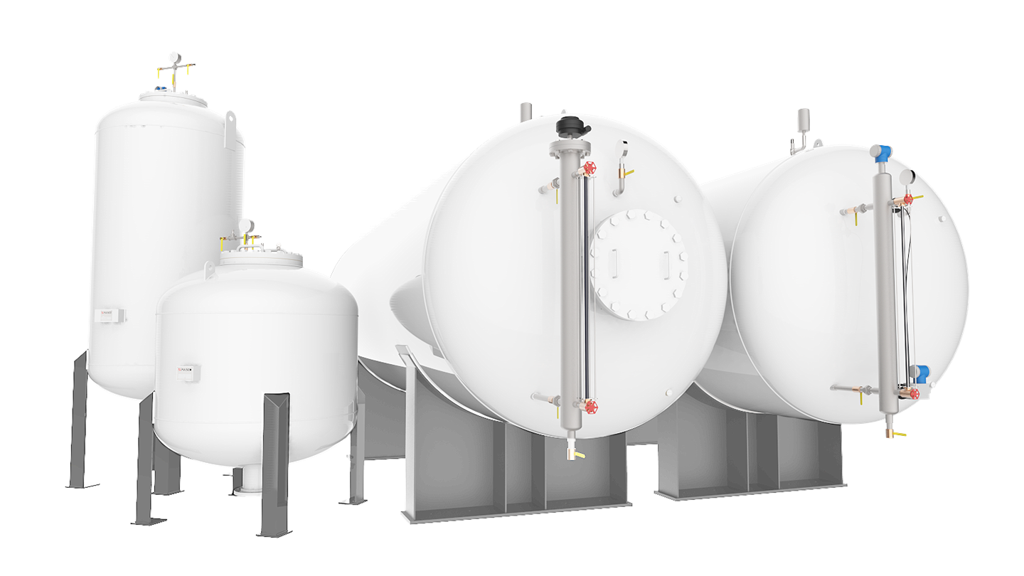
PULSCO’s Pressure Control Systems maintain the water pressure within a range by starting the booster pump on low pressure and stopping the booster pump on level in the tank. This level in the tank should correspond to the high pressure. If the pressure is below the high pressure, then air is added to increase the pressure to the correct value. If the pressure is above the high pressure, then air is vented from the tank to reduce the pressure to the correct value. PULSCO’s Pressure Control Systems (Hydropneumatic tank) is a control and feedback application that maintains water system pressure within a specified range. The system is used to minimize excessive pump cycling and provide high pressure water. Typical applications for PULSCO’s Pressure Control Systems are: o Water Treatment Plants o Small Community Water Supplies o Fire Suppression Equipment o Industrial Applications HYDROPNEUMATICPressure Control SystemAPPLICATIONFEATURE - BenefitOPERATIONaircompressor tankleveltransmittersightglassCPTTANK – a steel pressure vessel constructed in accordance with ASME, Section VIII, Div. 1 Pressure Vessel Code Requirements and to the working pressure necessary for the required service. SIGHT GLASS – for visual indication of tank water level and extends the full operating range of the system. LEVEL TRANSMITTER – used to provide the feedback information necessary for water level control in the tank. Several alternatives are available to transmit the water level information to the control panel including conductance probes, a differential pressure transmitter or a capacitance probe. AIR COMPRESSOR – an air cooled, two-stage, reciprocating type with air receiver. The compressor works in conjunction with the unit control panel and provides the air for the add-air function of the control system. ADDITIONAL FEATURES – pressure transmitter, safety, solenoid, and ball valves are provided to complete the system package. The air charge and water level within the tank is maintained by the Unit Control Panel (Relay logic or PLC controlled). unitcontrolpanelpressuretransmitterPULSCO’s Hydropneumatic Pressure Control Systems range from single to multiple tank configurations and vary in tank size from: o 400 to 50,000 gallons o 3 to 13 foot diameter o 6 to 60 foot long Each tank is designed for a specific application to provide the most economical and reliable configuration. The inlet/outlet nozzle can be placed almost anywhere on the shell or head (shown on shell). All tanks include a manway, welded support saddles and lifting lugs. Both horizontal and vertical equipment orientation is possible. VARIABLESHYDROPNEUMATICPressure Control SystemHYDROPNEUMATIC TANK REQUIREMENT:OPERATING PARAMETERS:740-0901Provide the following to size the pressure tank volume: a.) Required Useable Volume (drawdown between pump starts): Gallons Cubic Feet b.) Operating Pressure Range: psig to psig OR provide a.) Total Pressure Tank Volume: Gallons Cubic Feet b.) Outside Diameter: inches Number of Pumps: Capacity of Each Pump: GPM Shut Off Head: GPM Design Pressure (Maximum Allowable Working Pressure): PSIG (10% or 30 psig above maximum operating pressure) Orientation: Horizontal on saddles Vertical on legs Inlet / Outlet Connection: Size: inches Flange Rating: 150# 300# Other Location: Bottom Side End Manway: Elliptical 12x16 Ellipt ical 14x18 Elliptical 18x2 Other Interior Lining: Sandblast; Coatings 1st coat: 2nd coat: (if required) Exterior Paint: Sandblast; Coatings 1st coat: 2nd coat: (if required) Pressure Control: Automatic Manual PUMP DATA:COMMENTS:CPTPULSCO, Inc. I 17945 Sky Park Circle I Suite G I Irvine I California I 92614 I USA I Ph: 949.261.1717 I TF: 877.PULSCO.2 sales@pulsco.com I www.pulsco.com Page 1 Page 2
Most popular related searches