

- Home
- Companies
- Qubino by GOAP
- Products
- Qubino - 3-Phase Smart Meter
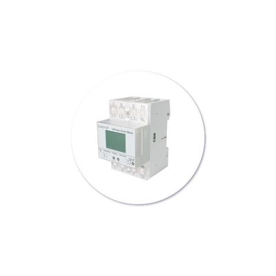
Qubino - 3-Phase Smart Meter
The smart way to control the consumption of three devices, a single 3-phase device or your entire home running on a 3-phase power network.
Measure your entire home running on a 3-phase electric power network
Lower the amount of energy you use. With Qubino 3-Phase Smart Meter you can remotely measure the energy consumption of your home.
Champion of precision
The most accurate Z-Wave 3-phase Smart Energy Meter in the world.
It`s the only 3-phase energy meter on the market that the current passes through it.
No current clamps needed.
It measures much more than W and kWh.
It measures 9 different values:
V, A, W, var, PF, kWh import, kWh export, kVAh, kvarh.
Lower consumption
and save energy
By adding additional contactors IKA or BICOM, Qubino 3-Phase Smart Meter can automatically turn devices off after they exceed the set power consumption.
For example, the heating will automatically turn off after it reaches the set power consumption value.
Main terminals (L1I, L2I, L3I, NO, L1O, L2O, L3O, NO)
Contacts capacity: 2.5 ... 16 (25) mm2
Connection screws: M5
Max torque: 3.5 Nm (PZ2)
Optional terminals (1,2,4,5)
Contact capacity: 1 ... 2.5 mm2
Screws: M3
Max torque: 1.2 Nm
Measuring input:
Type (connection): three phase (4u)
Basic current (Ib): 5 A
Maximum current (Imax): 65 A
Minimum current (Imin): 0.25 A
Starting current: 20 mA
Nominal voltage (Un): 3x230 V/400V
Power consumption at Un: < 8 VA
Nominal frequency (fn): 50 and 60 Hz
Accuracy:
Active energy and power:
Standard EN 62053-21: class 1
Standard EN 50470-3: class B
Reactive energy:
Standard EN 62053-23: class 2
LED:
Colour: red
Pulse rate: 1000 imp/kWh
LED on: no load indication
Optical communication:
Type: IR - used to control BICOM432-40-IR
Input (16):
Rated voltage: 230 V (± 20%)
Input resistance: 450 kOhm
Safety:
LCD:
Indoor Meter: yes
Degree of pollution: 2
Protection class: II
AC voltage test: 4 kV
Installation Category: 300 Vrms cat. III
AC voltage test: 4 kV
Installation Category: 300 VRMS Cat. III
Standard: EN 50470
Ambient conditions and EMC:
According standards for indoor active energy Meters.
Temperature and climatic condition according to EN 62052 11
Ambient conditions and Safety:
According standards for indoor active energy Meters.
Temperature and climatic condition according to EN 62052 11
Dust/water protection: IP50
Operating temperature: -25 ... 55°C
Storage temperature: -40 ... 70°C
Enclosure material: self-extinguish
complying UL94 V
Indoor Meter: yes
Degree of pollution: 2
AC voltage test: 4 kV
Standard: EN 50470
Distance: up to 30 m indoors (depending on building materials)
Weight (with packaging): 220g (240g)
Frequency range: 868.4 MHz*, Z-Wave
Installation: DIN rail 35mm
Dimensions (W x H x D): 53,6 x 84 x 65mm
Package dimensions (W x H x D): 58 x 84 x 95mm
Colour RAL 7035
ORDERING CODE (MODELING NUMBER): Z-WAVE FREQUENCY
ZMNHXD1: 868.4 MHz
ZMNHXD2: 921.4 MHz
ZMNHXD3: 908.4 MHz
ZMNHXD4: 869,0 MHz
ZMNHXD5: 916,0 MHz
ZMNHXD6: 868,4 MHz
ZMNHXD7: 919,8 MHz
ZMNHXD8: 865,2 MHz
ZMNHXD9: 922,5 MHz
ZMNHXDA: 919,7 – 921,7 – 923,7 MHz
ZMNHXDB: 868,1 MHz
ZMNHXDC: 868,1 MHz
ZMNHXDD: 919,8 MHz
ZMNHXDE: 920,9 MHz
Parameter no. 7 – Input 1 switch function selection
Available configuration parameters for input switch I1
Values (size is 1 byte dec):
Default value 0
- 0 - disabled
- 2 - IR external relay control – mono stable push button
- 3 - IR external relay control - bi stable switch
- 4 - External relay control – mono stable push button
- 5 - External relay control – bi stable switch
NOTE: By setting the parameter 7 to value 4 or 5 the external Relay (IKA) is working with input switch without enabling parameter no. 101
NOTE: To make the IR Relay (BICOM) responsive to the digital input, in addition to the setting of the configuration parameter 7, parameter 100 must also be set to value 1 or 2.
Parameter no. 40 – Reporting on power change
This parameter is valid for Active Power Total, Active Power Phase1, Active Power Phase2 and Active Power Phase3.
Set value means percentage from 0-100 = 0% - 100%
Available configuration parameters (data type is 1 Byte DEC):
- Default value 50
- 0 – reporting disabled
- 1-100 = 1% - 100% reporting enabled. Power report is send only when actual power in Watts (in real time changes for more than set percentage comparing to previous Active Power, step is 1%.
NOTE: if power change is less than 5 W, the report is not send (pushed).
NOTE: Device is measuring also some disturbances even if on the output is no load. To avoid disturbances:
- If measured Active Power (W) is below e.g. 5W-> the reported value in this case is 0W
The module is measuring some disturbances even if on the output is no load. To avoid unintended reporting: If measured active power (W) is below 5 W -> the value is not reported.
Parameter no. 42 – Reporting on time interval
This parameter is currently valid only for Active Energy Total Import/Export (kWh), Reactive Energy Total (kvarh), Total Energy (kVAh)
Available configuration parameters (data type is 2 Byte DEC)
- Default value 600 (600 seconds - 10 minutes)
- 0 – reporting disabled
- 600-32535 = 600 (600 seconds – 32535 seconds). Reporting enabled. Report is send with the time interval set by entered value.
NOTE: Device is reporting only if there was a change of 0.1 in Energy
NOTE: In the future will be possible to measure and report also Active Energy on PH1, PH2 and PH3.
Parameter no. 43 – Other Values - Reporting on time interva
This parameter is valid only for Voltage (V of ph1, ph2, ph3), Current (A of ph1, ph2, ph3), Total Power Factor, Total Reactive Power (var)
Available configuration parameters (data type is 2 Byte DEC)
- Default value 600 (600 seconds - 10 minutes)
- 0 – reporting disabled
- 600-32535 = 600 (600 seconds – 32535 seconds). Reporting enabled. Report is send with the time interval set by entered value.
- Note: Device is reporting only if there was a change
Parameter no. 100 – Enable / Disable External IR relay (BICOM)
Available configuration parameters (data type is 1 Byte DEC):
- default value 0
- 0 – External IR relay disabled
- 1 – External IR relay enabled and connected to all 3 Phases
- 2 – External IR relay enabled and connected to a Phase 1
NOTE1: After parameter change, first exclude module (without setting parameters to default value) and then re include the module.
NOTE 2: If you don`t have IR BICOM relay module mounted and you enable IR communication (parameter 100 is 1 or 2) there will be no valid IR relay state reported. It will be reported IR COMMUNICATION ERROR and LED2 will BLINK.
Parameter no. 101 – Enable / Disable External relay (IKA)
Available configuration parameters (data type is 1 Byte DEC):
- default value 0
- 0 – External relay disabled
- 1 – External relay enabled and connected to Phase 2
NOTE1: After parameter change, first exclude module (without setting parameters to default value) and then re include the module.
Parameter no. 106 – External IR relay (BICOM) power threshold settings – maximum power of all phases together
This parameter defines a threshold when External IR relay is being turned off. (If Parameter no. 100 is set to the value 1 or 2)
Available configuration parameters (data type is 2 Byte DEC)
- Default value 0
- 0 – no function
- 10-60000 – 10W-60000W
NOTE: Meter is capable of measuring max 3x65A!
Parameter no. 107 – External relay (IKA) power threshold settings – maximum power on phase L2
This parameter defines a threshold when External relay is being turned off (if the parameter no. 100 is set to the value 1 or 2).
Available configuration parameters (data type is 2 Byte DEC)
- Default value 0
- 0 – no function
- 10-20000 – 10W-20000W
NOTE: Meter is capable of measuring max 65A
Parameter no. 112 – Power threshold – Delay before power on
External IR relay/ External relay is turned off due to detected overload (as set by parameter 106&107) and remains off for a time, defined in this parameter. After that time, the output turns on to check, if the overload is still present.
Available configuration parameters (data type is 2 Byte DEC)
- Default value 0 (disabled)
- 0 – External IR relay/ External relay will not turn back on
- 30 – 32535 = 30 s – 32535 s
NOTE: the delay time may be prolonged for more then 10s of the time set by the parameter.
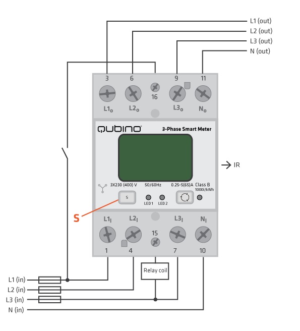
L1I, L2I, L3I: Live input
NI: Neutral input
L1O, L2O, L3O: Live output
No: Neutral output
16: Input for IR external relay/Ext. relay
15: Output for External relay (max. 3W)
S: Service button (used to add or remove device from the Z-Wave network)
LED1: Device status. For detailed information please check the chapter “LED SIGNALIZATION FOR INCLUSION/EXCLUSION”
LED2: External relay status. For detailed information please check chapter LED SIGNALIZATION FOR INCLUSION/EXCLUSION
IR: Output for IR external relay (BICOM)
1000imp/kWh: Red - Pulse rate (On – no load indication)