
- Home
- Companies
- Onda Corporation
- Products
- OndaSonics - Model MCT-2000 - Acoustic ...
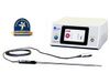
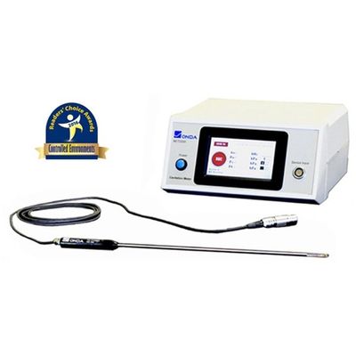
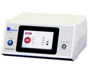
OndaSonics - Model MCT-2000 -Acoustic Cavitation Meter
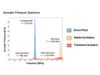
The MCT-2000 combines the power of a high speed digitizer, spectrum analyzer, and advanced microprocessor to produce an acoustic pressure spectrum. Different components in the spectrum are analyzed to quantify the fundamental frequency and pressure from the direct field, stable cavitation, and transient cavitation. Specifically, the pressure within the fundamental frequency peak represent the direct field pressure from the sound wave. The harmonics, sub-harmonics, and ultra-harmonics represent the stable cavitation, or the cavities that oscillate in size and dimension. Finally, the broadband white noise in the spectrum represent the transient cavitation, or the cavities that implode and collapse.
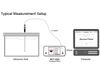
The advanced MCT-2000 acoustic cavitation meter addresses the critical need to quantify the cavitation performance used in ultrasonic cleaning and sonoprocessing applications. Coupled with a calibrated HCT-0320 hydrophone, four key parameters are determined instantaneously:
- Fundamental Frequency, FO
- Direct Field Pressure, PO
- Stable Cavitation Pressure, PS
- Transient Cavitation Pressure, PT
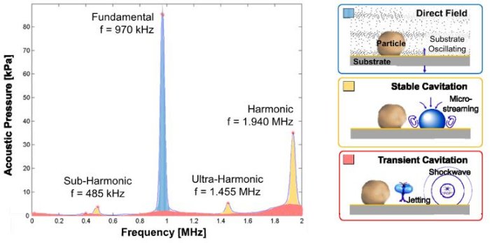
This is done by analyzing the calibrated acoustic spectrum which captures different pressure components. Mechanical sound waves induced by transducers oscillating at the fundamental frequency generate the direct field pressure. Rapid changes in pressure within the liquid create cavities or “cavitation”. Stable cavitation represents a cavity oscillating in size and shape, resulting in micro-streaming effects. Transient cavitation occurs beyond a pressure threshold, where the cavities collapse creating jetting effects and shockwaves.
- Characterize ultrasonic and megasonic cleaning tanks, sonoprocessing systems, and other devices that rely on acoustic cavitation.
- Determine the primary cleaning mechanism by comparing the level of direct field pressure, stable cavitation pressure, and transient cavitation pressure.
- Develop and continuously monitor the process window to maximize particle removal and limit damage
- Routinely spot check the acoustic field of cleaning tank for process control monitoring
MCT-2000 Cavitation Meter
- Measured Parameters:
- Fundamental Frequency, FO (MHz)
- Driving Field Pressure, PO (kPa)
- Stable Cavitation, PS (kPa)
- Transient Cavitation, PT (kPa)
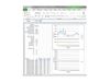
- Data Management:
- Touch panel display
- Time averaging interval: 1-60 sec
- Data logging to local memory
- Save parameters, spectrum, waveform
- Export as text or binary
- Remote access for maintenance
- Power: AC power plug
- Dimensions: 232 mm (W) x 113 mm (H) x 215 mm (D)
- Application(s): R&D, process development, reference
- Measurement Parameters:
- Frequency, F0 (kHz)
- Direct Field Pressure, P0 (kPa)
- Stable Cavitation Pressure, Ps (kPa)
- Transient Cavitation Pressure, Pt (kPa)
- Hydrophone Interface:
- Compatible with HCT Hydrophone
- Connector with embedded calibration file
- Electronic Bandwidth: Up to 10 MHz
- Data Management:
- Touch panel display
- Time averaging interval: 1-60 sec
- Data logging to local memory
- Traceable calibration to NPL in the UK
- Remote access via Ethernet
- Save: Parameters, spectrum, waveforms
- Power: AC Power Plug, 110-220 VAC
- Dimensions: 232 mm (W) x 113 mm (H) x 215 mm (D)
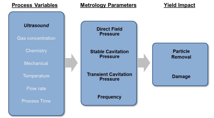
Ultrasonic cleaning relies on the mechanical agitation from sound pressure that disrupts the surface boundary layer to allow particles to detach and flow into the bulk fluid.
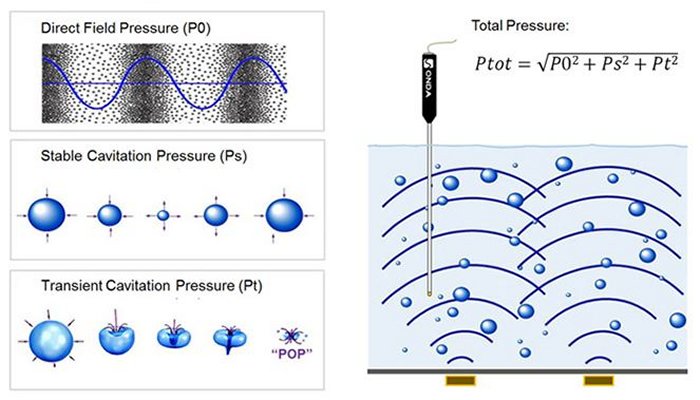
There are 3 primary forms of ultrasonic pressure that contribute to this:
- Direct Field Pressure (P0) – Vibrations from oscillating transducers mounted to the cleaning tank are transferred to the cleaning liquid to create acoustic pressure waves. These sound waves oscillate at the drive frequency of the tank, rapidly changing in pressure (P+ to P-) and creating cavities or “cavitation” within a liquid. The cavity size is a function of the Fundamental Frequency (F0).
- Stable Cavitation Pressure (Ps) – Micro-bubbles (or cavities) in the liquid, generated from the direct field pressure, oscillate in size and shape causing the surrounding fluid to move. This results in strong shear forces in the vicinity of a solid surface, removing particles. This form of cavitation is also known as non-inertial cavitation.
- Transient Cavitation Pressure (Pt) – When the acoustic field is strong enough (i.e., beyond the “cavitation threshold”), the cavities may oscillate to the point where they collapse resulting in shock waves that dislodge particles from a solid surface. This form of cavitation is also known as inertial cavitation.
At a given time, all mechanisms may actively contribute to particle removal overcoming attractive van der Waals, capillary, and electrostatic forces.
Please view the video that describes the various mechanisms which contribute to cleaning.
The influence from each mechanism will depend on conditions such as the drive frequency, electrical input power, gas concentration, chemistry, temperature, and other process variables. For instance, it is generally recognized that transient cavitation is more prevalent at ultrasonic frequencies (20-500 kHz) while stable cavitation dominate at “megasonic” frequencies (> 500 kHz). This is why higher frequencies are more common for precision cleaning processes that are sensitive to damage.
The advancement of ultrasonic and megasonic cleaning processes for applications (semiconductor, masks, storage devices, solar cells, etc.) drive the need to characterize the acoustic performance under complex process conditions. The primary cleaning mechanism is achieved by applying ultrasonic energy to the cleaning solution. These sound waves generate cavitation, where bubbles are formed and either oscillate or implode, dislodging and removing contaminants from the substrate surface.
Ongoing research is being conducted to understand how variables such as the acoustic pressure, drive frequencies, and concentration of dissolved gases affect the cleaning efficiency. To control advanced wet clean processes, such as semiconductor and electronic cleaning, upper and lower controls are established to not only ensure maximum particle removal efficiency (PRE) but also to limit any damage on fragile features or surfaces. Establishing and controlling a process window has proven to be critical to maintain high device yields.