

- Home
- Companies
- E. Beaudrey & CIE.
- Products
- Beaudrey - Differential Level Measuring ...
Beaudrey - Differential Level Measuring Systems
Safe operation requires that when the head-loss reaches a preset value, the cleaning cycle is started and carries on for a minimum period of time or until the head-loss has dropped back to clean machine values.
Cleaning screens and filters is controlled in three manners:
- Operator: The operator manually initiates a cleaning cycle.
- Timer: A timer starts a cleaning cycle periodically. The periodicity is preset and generally adjustable.
- Head-loss: The head-loss of any screen or filter increases as more debris are arrested and more mesh surface is obstructed.
There are two main cases:
Gravity-fed screens (trash rakes, travelling band screens, drum screens, WIPs etc.)
The head-loss is measured as the level difference between the water surfaces upstream and downstream.
Various systems are available:
- Float and pneumatic types which are now obsolete.
- Ultrasonic or radar types which have the advantage of not being in contact with the water.
- Piezometric systems for which the sensors are immersed and require regular cleaning. To be used only when the previous systems do not fit.
All these systems require special expertise to manage the interference between neighbouring systems and other obstacles (foam, etc.). BEAUDREY can supply the proper solution.
BEAUDREY has worked with a highly-reputable supplier to produce the sensors specially suited to screen applications. The signals received from the sensors are processed by either:
- A dedicated black box
- The screen control PLC (Programmable Logic Controller) in the control cabinet
- The plant’s DCS system (Distributed Control System)
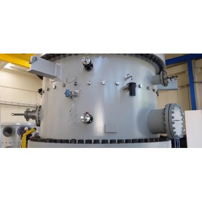
For pressure-line filters, self-cleaning strainers, debris filters and tube-cleaning systems the head-loss is measured as the difference in pressure between the upstream side and the downstream side of the machine.
In practice, it is always done using a differential pressure membrane pressostat. Two layouts are possible
- Each side of the pressostat is connected directly to each side of the machine shell. The pressure transmission pipes need periodical maintenance if growth or deposit occur.
- The pressostat is connected to silicone-filled capillary tubes, each of them transmitting the pressure applied on a membrane installed on the shell’s corresponding pressure-sensing branch. The solution is more costly but much easier to maintain. Extreme care must be taken in selecting the membrane’s material.
Signal processing is the same as for the gravity-fed screens above.