

EMP Industries, Inc.
EMP - Boat Wash Pad
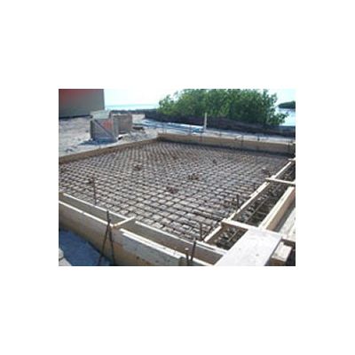
A wash pad should be considered an integral part of a wash rack operation. this seemingly non purposeful object is typically disregarded as a root spot where to park the device you are about to wash. This is the furthest from the truth when considering filtration capacity of the surface area and the potential means by which the wash water management is initially generated. This document is designed to provide the basic information about the wash pad, its design characteristics and the integration of this main component to any wash water operation. The wash pad shown here is considered a properly designed wash pad. the following bullet point describe why.
Most popular related searches
wash pad
water treatment system
wash water recycling
wash water
water treatment
oil-water separator
rainwater
water recycling
settling tank
water management
- The grade of the pad is designed to move the water to one corner of the pad using a shallow slope, 1/8″ per foot, which allows solids to remain on the wash pad and not be swept off from aggressive flow. The wash pad itself should be used as a very large filter. The surface area and gradual slope filters many solids so that the water treatment equipment will not be overwhelmed with excess solids
- The wash pad is designed with a Rain Diverter that will remove storm water off the pad without entering the water treatment equipment. The design incorporated here shown in figure 2 uses a sliding gate that when closed blocks the path of the water to the trench and the grade of the wash pad then allows the water to leave the pad at the corner. The wash pad will need to be cleaned after each use so that when the wash pad is set up to receive rain water, the rain water will not flush previous wash contaminates off the pad to the storm drain. This practice is described in the Florida Department Of Environmental Protections best management practices for wash water recycle operations. See figure 4. Similar EPA instructions are written for each state.
- The trench shown in this wash pad design becomes the second phase of wash pad filtration by again generating a shallow grade, 1/8″ per foot slope, to allow solids to settle in the trench before reaching the water treatment equipment. The trench is designed so that no water is allowed to collect in the trench itself. The trench can also be fitted with removable weirs set in the bottom of the trench to further enhance the filtration by creating treacherous paths where solids will tend to accumulate. the weirs can simply be 2″ angle iron that can easily be removed to allow a square nose shovel to be used for collected solids removal. A shop vacuum also works well to remove solids from the trench.
- An in ground separation/settling pit can be used in place of the trench to allow for oil/water separation through baffling or solids settling through the use of water volumetric. Using water volumetrics for settling increases the potential for BOD generation through reduced dissolved oxygen in the volume of water in the pit. Using water volumetrics also increases the amount of wet sludge that would eventually need to be hauled off site. Allowing solids to remain in a settling tank for long periods of time increases the contaminant levels in the sludge as more solids are added. Increased contaminant levels increases the amount paid to have the solids hauled off site. Solids that settler on a properly designed designed wash pad contain less contaminants and would be easier to discard.
- A sump at the end of the trench is used to collect and transfer the water treatment equipment. the pump in the sump should be elevated off the bottom of the sump to allow for some solids to settle below the suction of the pump. The sump should regularly be cleaned to remove collected solids before reaching the sump suction.