

- Home
- Companies
- Cropscan, Inc.
- Products
- Cropscan - Model 2000 - Data Logger ...
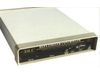
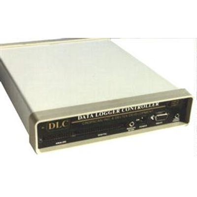
Cropscan - Model 2000 -Data Logger Controller (DLC)
The DLC system couples the latest micro-computer technology and analog/digital electronics with customized software. This system provides a range of support for the most casual of users to the requirements of the most demanding. For most data collection operations, use of the menu driven operational control program is all that is needed to configure the system parameters and to collect data. Where data conversions or specific output control is required, equations or control programming may be added to the DLC operational control program in the form of simple BASIC language statements.
- Newer CPU: 2-3 Times Performance Improvement over older Model 92
- Maximum Memory Size Doubled to 512K Bytes (81,920 data points)
- Memory Card Changed from Epson 40-pin to 68-pin PCMCIA SRAMOlder Model (92) Can be Upgraded, Except for Memory Card Connector (ContactCROPSCAN, Inc.for pricing and to arrange for upgrade)
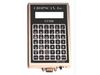
Operator interface to the DLC is through a computer or hand terminal (locally by RS232 serial or remotely through use of modems).
- Versatile
- Flexible
- Programmable
- Portable
- Easy-to-use software
- Multiple applications
- Battery operated
- Low power consumption
The DLC software platform is implemented as a BASIC language interpreter with numerous data acquisition and control extensions to the language. Performance critical functions are implemented in machine code for the best possible performance. A feature of the DLC system platform is that it allows you to either extend the DLC operational control program or create your own program(s) to tailor the menus, user interface, or operational characteristics uniquely to your needs, all in the BASIC language .. The DLC provides for 30K bytes of BASIC language programming space (much like running a BASIC program on a personal computer). Programs or data can be stored or loaded using optional solid-state credit card sized memory cards.
Example conversion equation and heater control:
- REM Convert Linear Temperature Sensor
- REM (Kelvin) Output to Fahrenheit
- 10101 X(2)=-463.4472+.1788618*X(2)
- REM Heater Control (Digital Output 5)
- 10102 IF X(2)>73 THEN DIG W,5,0
- 10103 IF X(2)
If temperature (channel 2) goes below 69 (degrees F) then turn heater on. If temperature goes above 73 then turn heater off.
- HIGH-LEVEL INTERFACE
- Menu prompt interface.
- Unique application programmability in high level MCS® BASIC-52 language.
- MEMORY CARD CAPABLE
- Memory card connector slot provided for solid-state battery powered (at least 1.3 year data retention) credit card sized memory cards.
- Used somewhat like diskettes, these memory cards allow for quick and easy data or program storing or loading.
- CONCURRENT OPERATIONS
- Scanning and recording operations can continue during communications.
- MULTIPLE INPUT/OUTPUT
- 16 analog inputs,
- 4 digital inputs,
- 4 digital outputs,
- 2 pulse counters, and
- 2 excitations (5VDC,AC)
- OUTPUT CONTROL
- Table driven or user programmable.
- Digital outputs can be turned on/off by use of a timed-output control table.
- Other digital output control can be done by user-written programming (in BASIC).
- EXPANDABLE
- Add programmable gains (1,10,100,1000) by plug-in expansion feature cards.
- System memory expandable from 32K to 512K.
- AUTO-FEATURE DETECT
- Automatic detection of feature cards installed,
- No hardware configuration jumpers or switches.
- AUTO RE-START
- Detection of power failure and automatic re-start when power is restored.
- Power can be removed for up to several hours without loss of previously collected data.
- Automatically recovers from changing batteries during a scan.
- HAND-HELD OPERATIONS
- Lightweight (3.25 lbs. with internal batteries).
- Input for externally triggered scan initiate source (hand-held pushbutton scan start option).
- Internal speaker and earphone jack output for audible scan sequence feedback.
- PRINTER PORT
- A serial printer (or a parallel printer by use of a serial-to-parallel converter) may be attached to the DLC for local printing of data.
- FLEXIBLE COMMUNICATIONS
- Automatic baud rate detection so contact can be made at any rate from 110 to 9600.
- DLC will automatically answer incoming calls but can also be configured to automatically initiate calls, with a configurable number of retries if a busy signal is received.
- The DLC can be configured to automatically turn power on and off to communication gear at various times and durations for power management.
- XMODEM data transfer support. Provides for data retrieval integrity with error detection and retransmittal over noisy communication lines.
- Communication session is maintained even when the DLC is remotely reset or a new operating program started.
- FAIL-SAFE MEASURES
- For controller applications, the DLC will continue to perform scans and exercise the controller functions even though the internal data storage memory is filled.
- Battery Cut-out Voltage configurable - The DLC will automatically discontinue scanning after the battery voltage has dropped below a certain point to preserve enough battery power to retain data collected and allow for data retrieval. All control digital outputs are automatically turned-off when this occurs to prevent controlled devices from being continuously left on.
- Inactivity detection - Automatically returns to sleep (terminates telephone or radio connection) if no communication activity occurs within a configurable amount of time (255 seconds default). Primarily to recover from communication line disconnects or to conserve on battery power or to provide security if the terminal is left unattended without ending the DLC session.
- Auto re-start - Automatic re-start of DLC upon return of power after a power failure or changing of batteries.
- SECURITY
- Password protection allowed with access attempt limited to three times per call.
- Failure counts are recorded.
- OPERATING RANGE
- TEMPERATURE: -40 to 70 degrees C (-40 to 158 degrees F)
- HUMIDITY: 0 to 100% non-condensing
- ANALOG INPUTS
- NUMBER OF CHANNELS: 16 single-ended.
- Difference between any two channel combinations can be done in software.
- VOLTAGE MEASUREMENTS (mV = millivolts, uV = microvolts)
- SAMPLE RATES
- Single A/D conversion = 28 microseconds.
- Multiple samples (averaged) per channel at 5985 conversions per second.
- Maximum channel scan rate (with data storage, single channel, continuous scan mode, 1 sample per channel) approximately 1.2 scans per second.
- Typical maximum scan rate (with data storage, 8 channels, continuous scan mode, 100 samples per channel) approximately 1 scan per second.
- INPUT RESISTANCE
- 20 giga-ohms (20 x 10^9 ohms)
- MAXIMUM SENSOR SOURCE RESISTANCE
- 1 mega-ohm (without affecting reading)
- DIGITAL INPUTS
- 4
- Expandable to 12 by installing the AIO - Additional I/O-Pulse Counters Feature Card.
- Inputs are active low (internal 100K ohm pull-ups).
- Can be activated by switch closure or by an active pull-down source.
- DIGITAL OUTPUTS
- 4
- Expandable to 20 by installing the AIO- Additional I/O-Pulse Counters Feature Card.
- Outputs are open collector, 30 volts maximum, capable of sinking 50mA.
- PULSE COUNTERS
- 2
- Expandable to 5 by installing the AIO - Additional I/O- Pulse Counters Feature Card.
- Schmidt trigger inputs (positive going threshold voltage = 3 volts (typical), negative going threshold voltage = 2 volts (typical))
- Hysteresis voltage = 1 volt (typical),
- 100K pull-ups to +5V.
- Counter increment on either switch closure or by active pull-down source (count increments on negative going input transition).
- Maximum sustained count rate = 28,400 pulses per second.
- Maximum burst count rate (to a total of 65,535 counts) is 8,000,000 pulses per second.
- Maximum counts between scans = 16,777,216
- OVER-VOLTAGE PROTECTION
- The base system analog inputs (16), digital inputs, and pulse counter inputs are resistor and diode clamped for protection against input voltages up to 86 volts, for short durations. The resistors serve as fuses (1/8 watt) and will burn out, to protect more sensitive circuitry, if over-voltage input conditions persist.
- EXCITATION
- +5V DC:
- 5.7V at 0mA load,
- 5.4V at 200mA (max), current limited,
- 0 volts when DLC is in the sleep mode (powered-down between scheduled scans).
- A direct short will cause the DLC to immediately power-down.
- AC:
- +/-5V square wave, unregulated 10mA maximum (trapezoidal, rise and fall transitions (slew) limited to .0025 V/usec),
- 10 to 100 hertz,
- Programmable in frequencies of 10, 11, 13, 14, 17, 20, 25, 33, 50, or 100 hertz or DC at +5 volts or DC at -5 volts).
- +5V DC:
- CPU
- Dallas DS80C320, 7.37 Mhz
- CLOCK
- Hours, minutes, seconds, month, day, and year in hardware with century and century roll-over in software.
- Accuracy: +/- 2 minutes per month.
- COMPUTER/TERMINAL INTERFACE
- RS232 serial,
- automatic baud rate detection (110-9600),
- 8 bits, no parity,
- XON/XOFF flow control,
- input buffering (allows key-ahead).
- BASIC INTERPRETER
- Intel MCS® BASIC-52 V1.1 (no charge) with
- CROPSCAN, Inc.DLC BASIC-52 Extensions.
- MEMORY
- 64K to 512K bytes RAM,
- 64K bytes ROM.
- First 32K of RAM is used as BASIC program space.
- Remaining RAM is used for data storage where there are 6 bytes per data point in floating point format (+/-1E-127 to +/-.99999999E+127.
- MEMORY CARD PORT
- 68 pin socket.
- Accepts PCMCIA SRAM memory cards
- Battery powered,
- 3V lithium,
- solid state credit card sized.
- Minimum battery life is 1.3 years, 3 years typical.
- Available in capacities of 64K, 128K, 256K and 512K byte sizes.
- PRINTER PORT
- Serial out, 0 to +5V.
- Baud rate configurable to 150, 300, 600, 1200, and 2400 baud
- 8 data bits, 1 start bit, 2 stop bits, No parity,
- Delay for carriage return (delay before transmission of next line) is configurable from 0 to 127 seconds, in 0.5 second intervals.
- A serial-to-parallel converter is available to allow connection to a parallel printer.
- MENU-DRIVEN SETUP
- All system configuration parameters can be set up in response to menu selections and parameter prompts.
- Direct command line input at anytime (allows even faster changes/setups as user becomes familiar with particular commands and parameters).
- MENUS:
- DLC Main Menu,
- Config-Status (display of current settings and important system information),
- ReConfigure,
- Communication-Link,
- Retrieve Data,
- Real-Time Data View,
- Security,
- Memory Card Operations.
- Additional sub-menus/prompts.
- MENUS:
- SCAN-RATES
- Selectable in 0-999 hours, minutes, or seconds (continuous scanning also selectable) with optional predetermined start date and time.
- INTEGRATE
- 0-999 scans that are to be averaged or considered for maximum and minimum reading captures. For example, with scan-rate set for each 10 seconds and integrate set at 6, the data recorded would be a one minute average based on 6 scans taken at 10 second intervals with maximum and minimum values, if configured, taken from the 6 scans.
- RECORDABLE ITEMS
- ID,
- Location,
- Date,
- Time,
- Digital Inputs,
- Digital Outputs,
- Pulse Counters 1, 2, 3, 4, or 5,
- Battery Voltage,
- +5V Supply Voltage,
- DLC Internal Temperature,
- Analog Channels 1 - 16, and
- AC Excitation Voltage. Max/min/average analog voltages, max/min/average pulse counts, and max/min/average internal temperature are also recordable (in conjunction with scan-rate and integrate settings).
- SAMPLES
- 1 - 65535 (number of A/D samples averaged for each channel scanned).
- Useful for acquiring an average if signal is not band-limited.
- Also useful for 50 or 60 hz rejection.
- Samples = 100 will average samples over 1 complete 60 hz cycle
- Samples = 120 will average over 1 complete 50 hz cycle.
- Sampling occurs at the rate of 5985 samples per second (A/D conversion takes 28 microseconds each).
- BATTERY CUT-OUT VOLTAGE - Initially set to 8.6 volts.
- SCAN-CYCLE HOOKS
Strategic program locations (BASIC language GOSUB locations) have been reserved for user-written code. These locations functionally serve as pre-scan, mid-scan, post-scan, and post-integration hook locations. This allows the user to add program statements to tailor the DLC’s logging or controlling operation for unique operations. For example, if a 10 second delay was required to turn on external device and allow the device/sensor/system to reach steady state, that delay would be added as pre-scan code such as:
12750 DIG W,1,1 REM Turn on device on digital output 1.
12751 TIME=0 REM Set internal second timer = 0
12752 IF TIME 12769 RETURN REM Continue (perform scan)Mid-scan hooks would typically be used to program sensor conversion equations (convert from millivolts to sensor type units) and/or output control statements. Converted values from the mid-scan hooks are then the data values stored. If no conversion equations have been programmed then the millivolt reading is stored as the data value.
Post-scan hooks would typically be used for scan-clean up activities.
Likewise, Post-integration hooks may be used for activities that may need to be done after an average of scans is completed.
- ON-TIME HOOK
- Allows for user-written programming functions to take place independent of normal auto scan cycle timing.
- TIMED-OUTPUT CONTROL TABLE
- Table that may contain up to 20 entries to control digital outputs in either one-time or cyclic on/off manner.
- Menu driven entry of starting date/time, on/off period/duration, and initial state.
- Allows for easy timed digital output control independent of normal auto scan cycle timing.
- RESETS:
- HARD RESET BUTTON (recessed in back panel) Restarts DLC, performing memory and diagnostic checks, any data in RAM is lost. Generally only used when RAM or ROM chips are changed.
- SOFT RESET BUTTON (recessed in back panel) Restarts DLC and attempts to pick up operation from where it last powered-off. Typically used during development of user programs. Data in RAM is NOT lost, if soft reset can successfully restart.
- BASIC LANGUAGE EXTENSION RESET COMMAND
- Reloads the basic DLC operating program from ROM into RAM and starts it.
- Current program, data, and operating parameters in RAM are lost.
- POWER REQUIREMENTS
- VOLTAGE: 9 to 15 volts (external input), any 12 volt battery can be used. To charge internal rechargeable batteries, if installed, requires external voltage input of 14.2 to 15 volts. Battery (NiMH) pack is available (primarily for portable use).
- CURRENT DRAIN: 42uA during sleep mode, 45mA during scans, and 67mA during RS232 communications.
- PHYSICAL SIZE - 7.25" x 9.75" x 1.75".
- WEIGHT - 2.75 lbs., 3.25 lbs. with battery pack.