

FirePro UK Limited
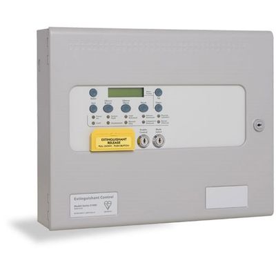
FirePro - Model Sigma XT+ ECU -Extinguishant Coincidence Unit
The Sigma XT+ ECU coincidence unit has two fully monitored inputs for connection to fire detection control equipment or addressable control modules to provide an EN12094-1 , EN54-2 and EN54-4 compliant extinguishant control system.
Most popular related searches
fire suppression system
fire suppressant
fire suppression
fire detection system
fire detection
fire control panel
epoxy coating
fire panel
- Its many programmable features and extensive range of inputs and outputs make the Sigma XT+ ECU coincidence unit suitable for all extinguishing applications where a fully featured control device is required.
- Among the many features of the Sigma XT+ ECU are serially connected status units for reduced wiring and reduced installation cost, dual extinguishant outputs that may be configured for main/reserve applications and a countdown timer which displays the time until discharge of the extinguishant in seconds.
- All units are independently configurable via a simple, code based programming interface to suit the desired application.
- Approved to EN12094-1, EN54-2 and EN54-4
- Dual extinguishant outputs
- First and second stage sounder outputs
- First and second stage relay contacts
- Main reserve facility
- Serial connection to status units
- Discharge countdown time indicator
- Product Code: K21001M2
- Size: 385mm(W) x 310mm(H) x 110mm(D)
- Construction: 1.2mm mild sheet steel
- IP Rating: IP30
- Finish: Epoxy powder coated
- Colour - lid & box: BS 00 A 05 grey - fine texture
- Colour - controls plate & labels: RAL 7047 light grey - satin
- Weight: 7kg
- Areas: 1
- Mains supply: 230V AC, 50Hz +10% - 15% (100 Watts max.)
- Mains supply fuse: 1.6 Amp ( F1.6A L250V)
- Power supply rating: 5.25 Amps total including battery charge 28V +/- 2V
- Maximum ripple current: 200 millivolts
- Battery type: 12 Volt sealed lead acid
- (Yuasa NP): in series
- Maximum Battery Capacity within Enclosure: Yuasa 7Ah
- Battery charge voltage: 27.6VDC nominal (temperature compensated)
- Battery charge current: 0.7A maximum
- Battery fuse: 20mm, 3.15A glass
- Current draw in mains fail condition: 54 milliamps
- Maximum current draw from batteries: 4 Amps
- Aux 24V output: Fused at 500mA with electronic fuse
- 1st and 2nd stage Sounder outputs: 21 to 28V DC Fused at 1A with electronic fuse
- Fault relay contact rating: 5 to 30VDC 1A Amp maximum for each
- Fire relay contact rating: 5 to 30VDC 1A Amp maximum for each
- Local fire relay contact rating: 5 to 30VDC 1A Amp maximum for each
- First stage contact rating: 5 to 30VDC 1A Amp maximum for each
- Second stage contact rating: 5 to 30VDC 1A Amp maximum for each
- Extract contact rating: 5 to 30VDC 1A Amp maximum for each
- Zone quiescent current: 0mA minimum, 2mA maximum
- Terminal capacity: 0.5mm2 to 2.5mm2 solid or stranded wire
- Number of sounders per circuit: Dependent on type and current consumption
- Monitored input end of line: 6K8 +/- 5% ½ Watt resistor
- Sounder circuit end of line: 10K +/- 5% ¼ Watt resistor
- Extinguishant output end of line: 1N4004 Diode
- Extinguishant release output: 21 to 28V DC. Fused at 1 Amp
- Extinguishant release delay: Adjustable 0 to 60 seconds (+/- 10%)
- Extinguishant release duration: Adjustable 60 to 300 seconds
- Monitored inputs normal threshold: (Allowable EOL) 10K ohm to 2K ohm
- Monitored inputs alarm threshold: 2K ohms to 150 ohms +/- 5%
- Monitored inputs Short circuit threshold: 140 ohms to 0 ohms +/- 5%
- Status unit/Ancillary board connection: Two wire RS485 connection (EIA-485 specification)
- Status unit power output: 21 to 28V DC, Fused at 500mA with electronic fuse
- Extract contact rating: 5 to 30VDC 1A Amp maximum for each
- Zone quiescent current: 0mA minimum, 2mA maximum
- Terminal capacity: 0.5mm2 to 2.5mm2 solid or stranded wire
- Number of detectors per zone: Dependent on type - typically 20
- Number of sounders per circuit: Dependent on type and current consumption - typically 20+
- Detection circuit end of line: 6K8 +/- 5% ½ Watt resistor
- Monitored input end of line: 6K8 +/- 5% ½ Watt resistor
- Sounder circuit end of line: 10K +/- 5% ¼ Watt resistor
- Extinguishant output end of line: 1N4004 Diode
- No. of detection circuits: Two to eight. 21 to 28V DC
- No. of sounder circuits: Dependent on model 21 to 28V DC
- Extinguishant release output: 21 to 28V DC. Fused at 1 Amp
- Extinguishant release delay: Adjustable 0 to 60 seconds (+/- 10%)
- Extinguishant release duration: Adjustable 60 to 300 seconds
- SIL, AL, FLT, RST inputs: Switched -ve, min resistance 0 ohms, max resistance 100 Ohms
- Zone normal threshold (Allowable EOL): 10K ohm to 2K ohm
- Detector alarm threshold: 1K ohms to 390 ohms
- Call point alarm threshold: 370 ohms to 150 ohms
- Short circuit threshold: 130 ohms to 0 ohms
- Head removal condition: 15.5 to 17.5 volts
- Cabling: FP200 or equivalent (max capacitance 1uF max inductance 1 mH
- Monitored inputs normal threshold (Allowable EOL): 10K ohm to 2K ohm
- Monitored inputs alarm threshold: 2K ohms to 150 ohms +/- 5%
- Monitored inputs Short circuit threshold: 140 ohms to 0 ohms +/- 5%
- Status unit/Ancillary board connection: Two wire RS485 connection (EIA-485 specification)
- Status unit power output: 21 to 28V DC. Fused at 500mA with electronic fuse