
- Home
- Companies
- DP CleanTech
- Products
- DP CleanTech - Flue Gas Cleaning System
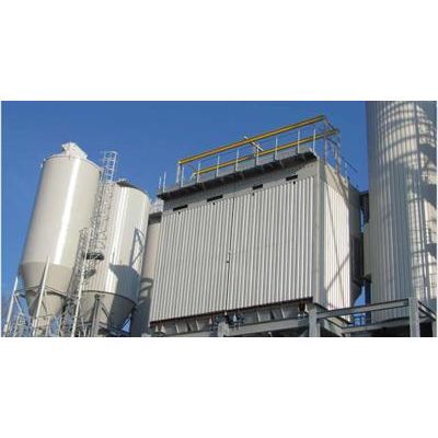
DP CleanTech - Flue Gas Cleaning System
DP`s specialized Flue Gas Cleaning team is based in the Midlands, UK. The team has extensive experience in redefining complex requirements in order to deliver specialized solutions, and has a proven track record in delivering reliable and cost effective systems for meeting emissions standards all over Europe. DP CleanTech has dedicated engineers within a specialized Flue Gas Cleaning division Their knowledge of state-of-the-art technologies to address the various regulations and requirements for emissions standards is unrivalled, and DP CleanTech solutions are deployed in many different plants around the world. DP`s experts are dedicated to meeting or exceeding these requirements, using the latest research and product design.
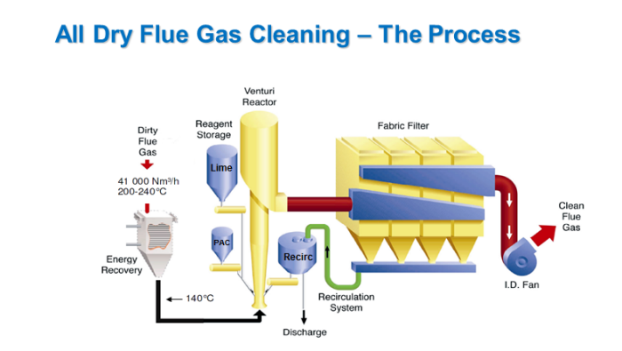
- Flue gas entering the reactor tower is cooled down to about 140°C.
- The flue gas enters the reactor tower where hydrated lime and activated carbon reagents bind with toxic acids and elements.
- Upon entering the filter, trapped particles form a dust cake allowing the neutralization and absorption reactions to complete.
- Captured product is recycled back into the tower via the recirculation surge hopper and screw conveyor allowing un-activated reagent to be utilized.
- Used product is discharged and collected by trucks after humidification.
- Treated flue gas exits the filter at a temperature of approximately 135°C and is finally discharged through the stack.
DP CleanTech integrates SNCR (Selective Non-Catalytic Reduction) systems into the top of the furnace, which injects ammonia or urea into the flue gas. This facilitates chemical bonding and the removal of NOx gases.
In a similar way, SO2 and HCL can be removed in a wet scrubber by using lime solution.
In addition, DP CleanTech’s advanced air systems are designed based on CFD modelling, which delivers a better combustion with low carbon monoxide emissions.
- Minimal maintenance cost and ease of operation
- Minimal moving parts
- Minimal moving parts
- Minimal plume formation
- Minimal plume formation
- Residue recirculation reduce reagent consumption
- Residue recirculation reduce reagent consumption
- Very high flexibility and resistance to cope with inlet pollutant peaks
- Very high flexibility and resistance to cope with inlet pollutant peaks
- Increased Energy Recovery
- Increased Energy Recovery
- Improved PAC efficiency and energy recovery
- Improved PAC efficiency and energy recovery
- Ease of integration reduces cost and lead times
- Ease of integration reduces cost and lead times