

- Home
- Companies
- Golden Harvest, Inc.
- Products
- Golden Harvest - Model GH-100 - Fully ...

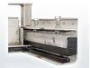
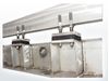
Golden Harvest - Model GH-100 -Fully Wedged Stainless Steel Sluice Gate
The GH-100 Fully Wedged Stainless Steel Sluice Gate by Golden Harvest, Inc. offers a well-engineered solution for controlled fluid passage in a variety of water management applications. In operation since 1988, this model is distinguished by its unique design characteristics that offer an efficient and economically viable alternative to traditional cast iron sluice gates. Unlike fabricated slide gates, it's a standard fabricated gate made from either type 304 or 316 stainless steel, dependant on the operating conditions. While not meeting the AWWA C-560 material requirements for cast iron, it conforms to the structural standards of the American Water Works Association for cast iron sluice gates. The GH-100 is equipped with adjustable wedge bars, conforming to AWWA C-560 requirements, ensuring durability and effectiveness. The product is assembled with a strong adherence to ANSI, American Steel Construction Specifications, and Uniform Building Codes, making it suitable for rigorous water management demands.- Heavy-duty Construction for Higher End Unseating Head Loads
- Leakage 1/2 of AWWAC-560 Standards For Cast Iron Gates Fully-adjustable Wedges and Pressure Bars
- Available in Type 304 or 316 Grades Corrosive Resistant Stainless Steel
The Golden Harvest, Inc. GH-100 Fully Wedged Stainless Steel Sluice Gate has been in the industry since 1988. The Model GH-100 offers some unique design features that have proven to be a reliable and cost effective alternative to the traditional cast iron sluice gate.
While this gate is a Standard fabricated and not cast iron, it should not be confused with a fabricated slide gate. The GH-100 sluice gate appurtenances meet the latest requirements of AWWA C-560. Depending on the water conditions the sluice gate frame and disc are fabricated from either type 304 or type 316 stainless steel. Although they do not meet the material requirements for AWWA C-560, which specifies cast iron, the structural design is in conformance with the American Water Works Association for cast iron sluice gates {ANSI/AWWA C-560, American Institute of Steel Construction Specifications ASD-Ninth Edition Uniform Building Code U.B.C. 97}. The model GH-100 is provided with adjustable wedge bars on the sides and top of the gate.
This section covers Wedged Stainless Steel Gates and operators. The equipment provided under this section shall be fabricated, assembled, erected, and placed in proper operating condition in full conformity with the drawings, specifications, engineering data, instructions and recommendations of the equipment manufacturer.
Gates and operators shall be supplied with all the necessary parts and accessories indicated on the drawings, specified, or otherwise required for a complete, properly operating installation, and shall be the latest standard product of a manufacturer regularly engaged in the production of fabricated gates.
Approved Manufacturers
Gates supplied under this section shall be Model GH-100 Wedged Stainless Steel Gates as manufactured by Golden Harvest Inc. or engineer approved equal.
Governing Standards
Except as modified or supplemented herein, all gates and operators shall conform to the applicable requirements of AWWA-C561 standards.
Quality Assurance
The manufacturer shall have 5 years experience in the production of substantially similar equipment, and shall show evidence of satisfactory operation in at least 10 installations. The manufacturer?s shop welds, welding procedures and welders shall be qualified and certified in accordance with the requirement of the latest edition of AWS Sections D1.1, 1.2 and 1.6.
The fully assembled gates shall be shop inspected, tested for operation and leakage, and adjusted before shipping. There shall be no assembling or adjusting on the job sites other than for the lifting mechanism.
Submittals
1. The manufacturer shall submit for approval by the purchaser, drawings showing the principal dimensions, general construction and materials used in the gate and lift mechanism.
2. The manufacturer shall submit for approval by the purchaser, complete engineering design calculations in compliance with AWWA standards latest edition.
Performance
Leakage: Sluice gates shall be substantially watertight under the design head conditions. Under the design seating head, the leakage shall not exceed 0.01 gallons per minute per foot of seating perimeter. Under the design unseating head, leakage shall not exceed 0.05 US gallons per minute per foot of perimeter.
Materials and Construction
General Design
Gates shall be either self-contained or non self-contained of the rising stem or non-rising configuration as indicated on the gate schedule. All parts of the gate shall have a minimum material thickness of 1/4 inch.
Wall Thimble
Wall thimbles shall be supplied by the gate manufacturer. Refer to the gate schedule for types and applicable locations. Minimum material thickness shall be 1/4 inch.
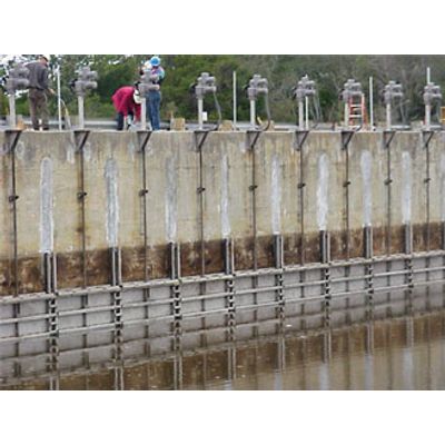
Frame
The gate frame shall be stainless steel and designed for maximum rigidity. The frame configuration shall be of the flush-bottom type and shall allow the replacement of the top and side seals without removing the gate frame from the wall or wall thimble.
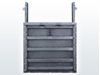
Slide
The slide shall consist of stainless steel plate reinforced to limit its deflection to 1/720 of the gate`s span under the design operating head. A neoprene resilient seal shall be attached to the bottom of the slide and be held in place with a stainless steel retainer bar.
Wedges
Gates with widths of 24-inches or greater subjected to unseating head pressure shall have a minimum of two intermediate top wedges. Wedges shall be stainless steel with ultra high molecular weight polyethylene faces and be fully adjustable.
Guides, Pressure Bars and Seals
The guides shall be provided shall be of such length as to retain and support at least two thirds (2/3) of the vertical height of the slide in the fully open position. Guide frame shall not weigh less than 13 lbs. per foot.
UHMW pressure bars shall be located inside the vertical guides. Jack bolts with locking bolts shall be provided for adjustability and to insure permanent setting.
Side and top seals shall be frame mounted and fully adjustable. Seals shall be resilient neoprene of the crown-type with a stainless steel retainer bar. Self adjusting compression cord seals or winged uhmw seals will not be considered.
The flush bottom resilient neoprene seal shall be mounted to bottom of disc and seal against the invert portion of the frame. Frame mounted invert seals will not be considered.
Yoke and Pedestal
The yoke, to support the operating bench stand, shall be formed by two structural members welded at the top of the guides to provide a one piece rigid frame.
Self-contained gates shall be provided with a yoke to support the operating bench stand. The yoke shall be formed by two structural members welded at the top of the guides to provide a one piece rigid frame. The maximum deflection of the yoke shall be 1/720 of the gate`s span.
Non-self contained gates shall be provided with pedestal mounted lifts. Pedestal shall be cast iron or mild steel and provided with shop coating.
Lifting Assemblies
Stem and Couplings
The operating stem shall be of stainless steel designed to transmit in compression at least 2 times the rated output of the operating manual mechanism with a 40 lb effort on the crank or handwheel.
The stem shall have a slenderness ratio (L/R) less than 200. The threaded portion of the stem shall have Acme type cold rolled threads with a maximum surface of 16 micro-inches.
Stems in more than one piece shall be joined together by solid couplings.
Gates having a width equal to or greater than two times their height shall be provided with two lifting mechanisms connected by a tandem shaft.
Stem Guides
Stem guides shall be fabricated from stainless steel. Stem guides shall be equipped with a UHMW bushing. Guides shall be adjustable and spaced in accordance with the manufacturer?s recommendation. The L/R ratio shall not be greater than 200.
Stem Cover
Rising stem gates shall be provided with a clear polycarbonate stem cover. The stem cover shall have a cap and condensation vents and a clear mylar position indicating tape. The tape shall be field applied to the stem cover after the gate has been installed and positioned.
Lifting Mechanism
Operators of the types listed in the schedule shall be provided by the gate manufacturer. Each manual operator shall be designed to operate the gate under the maximum specified seating and unseating heads by using a maximum effort of 40 lb on the crank or handwheel, and shall be able to withstand, without damage, an effort of 80 lb.
Gearboxes shall be provided when required to maintain the operating force below 40 lb. All bearings and gears shall be totally enclosed in a weather tight housing. Operator housing shall be cast steel or cast iron. The pinion shaft of crank-operated mechanisms shall be supported by roller bearings. The operating shaft shall be fitted with a 2 inch square operating nut and removable crank. The crank shall be fitted with a corrosion-resistant rotating handle. The maximum crank radius shall be 15 inches and the maximum handwheel diameter shall be 24 inches.
Part: Material
- Slide, Spigot, Frame, Stiffeners, Yoke, Guide angles.: Stainless Steel Type 304L ASTM A-276
- Side and Top seals: Neoprene ASTM D-2000
- Invert seal: Neoprene ASTM D-2000
- Bearing bars, Guides, Stem guide liner: Ultra High Molecular Weight Polyethylene ASTM D4020
- Bottom seal: Neoprene ASTM D-2000
- Threaded stem, Stem guides: Stainless steel ASTM A-276, Type 304L
- Fasteners: Stainless steel Type 304L
- Pedestal: Cast Iron ASTM A126, class B or Mild Steel A36/A36M
- Stem cover: Polycarbonate ASTM A-707
- Lift and stop nut: Manganeze bronze , ASTM B584, UNS-C86500