

- Home
- Companies
- HORIBA Europe GmbH
- Products
- HORIBA - Model GPS5 - Gas Sampling ...
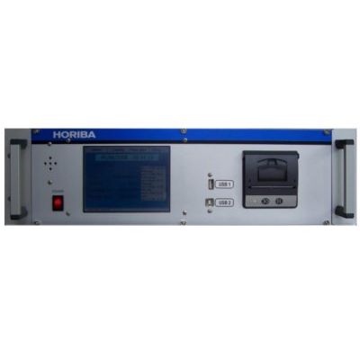
HORIBA - Model GPS5 -Gas Sampling System
HORIBA gas samplers are suitable for volume-correct taking of gaseous samples during emission and emission measurements. This device can be used wherever gases and gaseous components must be inspected.
Since this device is a innovation, its concept is based on the use of state-of-the-art technology. Thermal mass flow meters are used for the volume measurements, which refer to direct volume-correct measurements related to standard or operating liters. The control function is taken over by a microcomputer and the operation of the devise is carried out via the touch display on the front side. All important information, e.g. flow rate, collecting time, remain time, start time, etc. are indicated by means of an TFT display. This display also serves the purpose of programming the computer in plain text. A rotary slide valve pump is used as a suction pump, whereby the flow rate is regulated by the digital mass flow regulator. The devise can be equipped with up to 14 input channels. These channels can be activated by means of the timer control system up to 14 days in advance. The possibility of activating a measurement by means of an externally connected mA signal is also available (only as Option).
Flow sensors of the HI-TEC series F-200 operate according to the principle of heat transport, whereby the differential temperature T is measured in front of and after the sensor, a heated partial piece of a capillary tube. A part of the gas flows through the Sensor and is warmed up by the heater, while the rest runs though a bypass. Consequently the measured two temperatures drift apart. The temperature difference is directly proportional to the mass flow. Electrically, temperatures T1 and T2 are in fact two temperature dependent resistors. The signals measured in the sensor are amplified to electric signals. All common output signals are available and one can be selected. In the case of mass flow control, the output signal is continuously compared with a setpoint signal from a voltage source. Any deviations between setpoint signal and measured signal are translated into a control valve adjustment until the two signals are identical.
- Principle: measuring and controlling volume flow rates
- Data indication: display, integrated report printer and history memory
- Ambient temperature: 5 - 40 °C
- Power Input: 230V / 50 Hz max. 60 VA
- Weight electronic unit: 8,5 kg
- Dimensions: 500 x 420 x 135 mm
- Display: 5,7” TFT 640 x 480 Pixel with Touch
- Gas inlet: 14 x Span gas
- Flow range: 100 ml/min, and 1 - 5 l/min
- Report print: integrated