

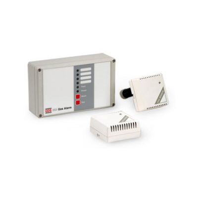
GDS - Model 202 -Flammable/Toxic/Regrigerant Gas Alarm
Toxic/Flammable/Refrigerant sensor combination. Standard Unit 1 - 10 Sensors. Four zone indicators. Single cable for multiple sensors. Individual Sensors with audible and visual warning alarms. Sensors pre-set and tested. Self diagnostic. Pre and full alarm indication. Two alarm relays. Wall or panel mount. Designed for ease of installation. System easily extended. Off the shelf system.
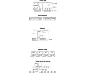
The GDS 202 gas leak detection system features a main control unit connected to remote sensors via a single 3 core cable. The control unit is of an advanced design using the latest technology and provides a high integrity system whilst enabling a significant cost saving over conventional gas alarm systems.
Standard sensors for use in commercial and light industrial applications such as laboratories, workshops, boiler plant rooms etc are available for monitoring toxic, oxygen, flammable or refrigerant gases. Each sensor incorporates a status LED and alarm sounder. Sensor types may be mixed and up to 10 in number for the standard control unit, or up to 20 when used with an optional auxiliary power pack. Alternatively sensors may be used separately without a control unit providing they are powered by a 12 or 24volt DC supply.
On power up, the green power indicator will flash for 3 minutes indicating that the sensors are stabililsing, during this timed period all alarm functions are held in the off condition.
After the stabilisation period, any sensor detecting gas will provide a local visual (red LED) and audible alarm, at the same time transmitting a signal to the control unit where a pre alarm is indicated by an intermittent audible alarm, with the red zone alarm LED flashing and the pre alarm relay changing state. Should the gas surrounding the sensor clear within 45 seconds the system will return to the normal operating condition. However, if the gas remains for longer than 45 seconds, full alarm condition will occur and be indicated by the red alarm LED and sounder going constant as well as the full alarm relay activating.
The audible alarm may be silenced at any time but full alarm indication will be latched until the gas has cleared after which the system may be reset by pressing the reset pad.
Control Unit - A two-part screw together polycarbonate enclosure houses the power supply alarm indicators, control functions, and alarm relays. The enclosure may be wall or panel mounted having cable entry from the rear, bottom, top or sides.
Standard Sensors - Two-part push together plastic enclosure that may be surface mounted using two fixing points or attached directly to a standard conduit box, cable entry is from the rear.
Control Unit
- Power Supply : 115/230vAC or 24vDC ±15%. The two voltages may be used at the same time (standby battery)
- Power Output : 24vDC-200mA max. - auxiliary equipment
- Frequency : 50/60 Hz
- Consumption : 3 watts
- Detector Head : l to 10 Toxic and/or flammable sensors
- Indicators :
- Power - (Green LED)
- Pre alarm - (Flashing red alarm LED and intermittent sounder) non latch
- Full alarm - (Constant red alarm LED and sounder) - latching (option non latch)
- Fault - (Amber LED and sounder) Fault monitoring - sensor/sensor cable/control unit - non latching
- Sensor Cable :
- 3 core 1 mm2
- Cable length - 200m max
- Alarm Relays :
- Pre alarm S.P.C.O (R1)
- Full alarm D.P.C.O (R2)
- Fault alarm S.P.C.O (R3)
- Relays are de-energised in non-alarm state (option-energised)
- All contacts rated -5A@230v AC.
- Relay Inhibit : Front Panel Access
- Protection : IP65
- Weight : 920gms
- Operation : -5 to +45°C
- Storage : +10 to +60°C
- Dimensions : L 200mm x H 120 mm x D 58 mm
- Miscellaneous : Remote test, remote inhibit, remote sounder, premanent mute
Sensor
- Power Supply : 12 to 30v DC
- Consumption : 1.2W
- Indicators :
- Power (Green LED)
- Gas Alarm (Green LED to red and sounder) - non latching
- Alarm Threshold : Preset (adjustable)
- Ambient Temp : Operation: -5 to 45°C Storage: +10 to +60°C
- Protection : IP42
- Weight : 115gms
- Dimensions : L 83 x H 83 x D36mm
The system may be electrically tested by pressing the test pad located on the control unit for 15 seconds, after which the pre-alarm state will be initiated with the exception of the relay, by maintaining pressure on the test pad for a further 15 seconds a full alarm condition will result including the operation of both relays.
Each sensor has an individual test switch which when pressed simulates gas present and turns the green LED to red and switches the sounder on.
To ensure that the system responds correctly to the presence of gas, each sensor should be exposed to test gas. It is advisable to carry out this test at least every six months.
During test periods alarm relays may be inhibited by pressing the reset pad for four seconds after which the fault indicator will illuminate and maintain all relays in the normal non-alarm state.