
GEM - Model EM -Portable Very Low-Frequency Electromagnetics Instruments
Ground and Airborne Conductor mapping and Cost Effective Resistivity Solutions. Very Low Frequency Electromagnetics (VLF) is a geophysical ground probing technology that utilizes VLF signals in the 15 to 30 kHz range normally used for communication with submarines. The signal generated is suitable for making geophysical measurements globally.
VLF is used in many applications, including mineral exploration, water exploration and more.
In mineral exploration, VLF data are used to map geologic structure, including the apparent dip of fault zones and shear zones. The data can be interpreted to identify the dip of these structures for reliable drilling. Data are also used to identify conductive ground which might correspond to sulphide concentrations. A third application is to map overburden in preparation to drilling and further sampling.
In groundwater exploration, VLF plays an important role. It can be used to detect conductive bodies of fluid – containing water – in bedrock or in the vicinity of fractures. Another use is for contaminant mapping – contaminants often have lower resistivity than surrounding fluids.
All of these features have electrical contrasts with surrounding rocks – tending to be more electrically conductive or resistive – and are reasonable targets.
Depth of Investigation
Depth of investigation is controlled by the electrical “skin depth” of the local geology. It varies from shallow to in some cases > 100m depending upon the overall background resistivity of the subsurface. Typically 20-75 meters can be expected. Conductive overburden suppresses signals and depth penetration may be severely limited at times. VLF works best where rocks are resistive and overburden is minimal or is highly resistive.
GEM’s VLF systems measure a variety of parameters, including in-phase as a percentage of the total field, out-of-phase as a percentage of the total field, horizontal component (x), horizontal component (y), and field strength in pT. This is a powerful combination of parameters designed to maximize the effectiveness of any survey.
And GEM has also made advanced technology innovations in its software and hardware — giving an easy-to-use interface and increased accuracy. For example, we developed a chip-based tilt sensor to replace commonly used fluid-filled sensors which means that the detector can operate much faster.
VLF surveys may be run on airborne or ground platforms. GEM’s GSM-90AV is an example of an airborne version and the GSM-V is GEM’s ground version. Systems such as the GSM-19V and 19GV are multiparameter systems for magnetometer and gradiometer surveys. The airborne version is equipped with two sensors so it can be tuned to two VLF transmitting stations concurrently.
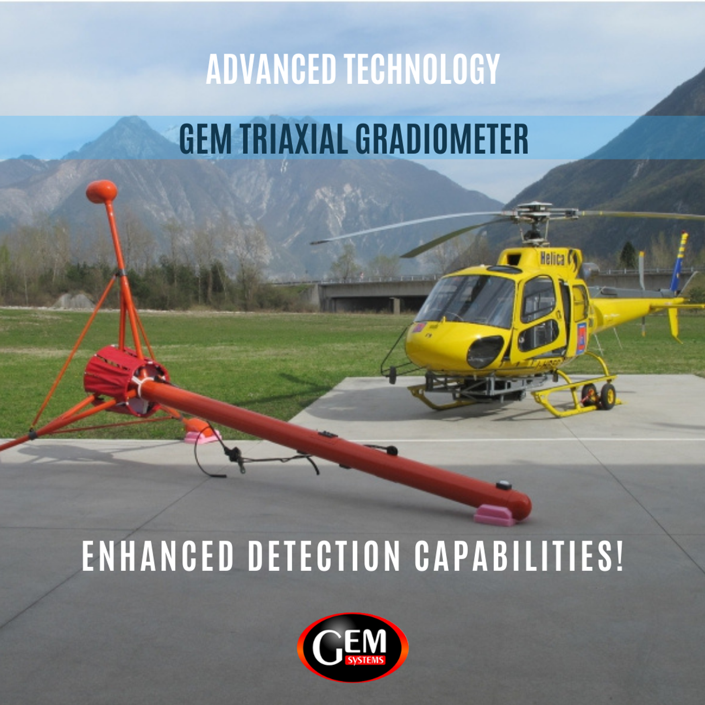
Airborne VLF
In the air, GEM’s VLF is used with its airborne optically pumped magnetometer and gradiometer systems with 10 Hz sampling. Two stations of data can be acquired simultaneously – maximizing the efficiency of the survey process.
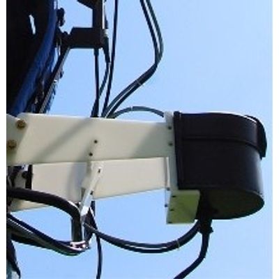
Other advantages of GEM’s airborne VLF include air-core sensors in contrast to a ferrite core used by competitors. The advantage of an air-core is that it does not introduce stray magnetic fields, and as noted, the recent innovation of a solid inclinometer gives the best in noise-free data.
View the Airborne VLF-EM with AIR COIL sensors
Ground VLF
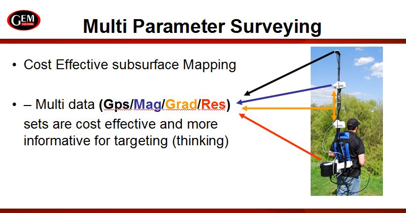
GEM’s VLF ground system is designed to be used by a single operator in a backpack configuration. Weight is nominal – 6.0 kg for a system with Walking VLF. The system is state-of-the-art in that it stores all data onboard in an expansive memory so that many days’ data can be saved at one time.
Because Walking Magnetometer/VLF measurements do not need ground contact, survey operation is very fast with no waiting time. This gives the maximum in productivity possible in a ground instrument.
GEM’s VLF can be towed with an all terrain or other ground vehicles. GEM’s ground solution has been implemented for use with its proven line of Optically Pumped Potassium, Overhauser, and Proton Precession technologies.
When surveying, it is important to remember that the VLF response is a maximum when the target strikes in the direction of the transmitter. Numerous transmitter choices, however, ensure that selection of a transmitter is rarely an issue.