

- Home
- Companies
- Al Matin Group
- Products
- Al Matin - Glass Reinforced Plastic ...
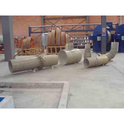
Al Matin - Glass Reinforced Plastic (GRP) Fittings
“FIBERTUBE” Fittings & Specials are available over a wide range of diameters, pressures & configurations. The cut & Miter process is extremely versatile for making the full range of diameters, standard & special shapes & custom designed parts. Fabrication of the fittings and specials starts with the production of “FIBERTUBE ” pipe that is cut and assembled into the desired configuration.
- The pipes are produced on continuous filament winding equipment with controlled metering of materials to ensure uniform properties and homogeneous material distribution on all sections of the fittings.
- Cut & Mitered fittings is made by cutting pipe sections to the desired form & pieces are jointed together with Contact Molding techniques using pre- approved material of chopped strand , woven roving reinforcement & the adequate quantity of Resin.
- The pipe (structure of the fitting unit) design is in accordance with AWWA M45 fiberglass pipe design manual. The design life is 50 years.
The Fittings are designed as a corrosion resistant piping system for conveying water or sewage under pressure or gravity flow in buried application.
Some uses for the pipe system are: sanitary sewers, storm water, potable water, raw water, Irrigation, Industrial wastes and effluent, sea water transmission, fire protection and cooling water.
For dimensions, please refer to Al-Matin fittings catalogue.
Thrust Restraints:
When the pipeline is pressurized, unbalanced thrust force occur at bends, reducers, tees, wyes, bulkheads and other changes in line direction. These forces must be restrained in some manner to prevent joint separation. When the surrounding soil cannot provide this restraint, thrust or stress/thrust block must be used. Determination of need and design of these restraints is the responsibility of the owner’s engineer subject to the following limitations.
Al-Matin Fiberglass Pipe’s. Engineering Dept. can assist in designing the restraint.
Thrust Blocks:
Thrust block must limit the displacement of the fittings to 0.5% of the diameter or 6 mm whichever is less. The block must completely surround the fitting fo r its entire length and circumference and should be placed either against un-disturbed earth or back-filled with pipe zone materials as appropriate for the native soil characteristics.
These blocks are applicable to:
- All bends, reducers, bulkheads and blind flanges.
- Tees, when the branch pipe is concentric to the header pipe centerline.
Note: It is not necessary to encase nozzle connection in concrete.
Nozzles are tee branches meeting all the following criteria:
- Nozzle diameter ≤ 300 mm.
- Header diameter ≥ 3 times nozzle diameter.
- If the nozzle is not concentric and/or not perpendicular to the header pipeaxis, the nozzle diameter shall be considered to be the longest chord distance on the header pipe wall at the nozzle/pipe inter-section.
Thrust Stress / Blocks:
Thrust/stress block must limit the dis-placement of the fitting to to that the coupling angles notations do not exceed the allowable . They must also restrict the radial deformation of the fitting to 0.5% of the radius of the respective pipe sections.
The block must completely surround the fitting for its entire length and circumference and should be placed either against un-disturbed earth or backfilled with pipe zone material as appropriate for the native soil characteristics.
These blocks are required for the following fittings when the line is ≥100 kPa (1 bar):
- Tees, when the branch pipe is eccentric to the header pipe centerline
- Lateral wyes
- Bifurcations
- Custom fittings as noted by special instructions
Pressure Class:
Pressure series are : PN ( 1 ,6 ,10 ,12 ,16 ,20, 25 and 32) Bar
Stiffness Class :
The stiffness classes are : SN (1250, 2500, 5000 and 10000) N/m² .
Diameter Range:
The nominal diameters covered by this specification are :