
- Home
- Companies
- Hebei GN Solids Control Co., Ltd.
- Products
- GN Solids - Model GNCM-40A - Drilling ...
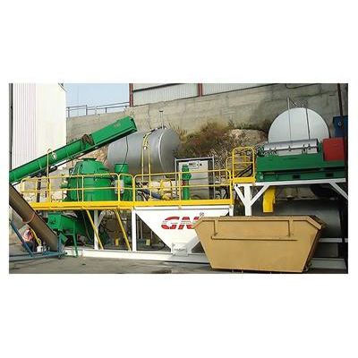
GN Solids - Model GNCM-40A -Drilling Cuttings Drying System
In order to maximise the recovery of valuable drilling fluids and reduce the volume of waste discharged, drilling contractors should adopt drilling waste management equipment to further treat the discharged waste cuttings from primary solids control equipment. After a long period of R&D, GN Solids Control have developed a standard complete skid mounted drilling waste cuttings drying system in which the vertical cuttings dryer and premier configuration decanter centrifuge are the key equipment.
- For oil based drilling cuttings, it can typically reduce the oil on the cuttings to between 3% - 5%.
- For water based drilling cuttings, it can reduce the moisture content for easy transportation.
- Recycling drilling fluids for reuse to save cost .
- Reduce the drilling waste quantity to save money on the disposal or further treatment.
Tank Skid Dimension: 11500x2200x2052mm
This dimension fit for putting inside a 40Ft container after removing the centrifuge and cuttings dryer for
shipping by sea.
Land Transportation Dimension: 11500x2300x3300mm
Lower the centrifuge and cuttings dryer to the low position when being moved, this dimension fit for
land transportation fast move completed package without removing centrifuge and cuttings dryer from
the skid.
Operation Dimension: 11500x4244x4567mm
This layout allows the drying solids discharge from the vertical cuttings dryer, and also allows the fluids discharged from the centrifuge goes to active/storage mud tank by gravity without transfer pump.
Drilling Cuttings Drying System Layout
- Primary Shale Shaker
- Desander & Desilter
- Solids Control Centrifuge
- Screw Conveyor/Auger
- Vertical Cutting Dryer
- Waste Decanter Centrifuge
Drilling Waste Cuttings Closed Loop Management Diagram (As shown in above picture)
- 1)The cuttings discharged from the primary shale shaker, desander and desilter were conveyed by a 3 unit screw conveyor to a cuttings dryer unit for treatment.
- 2)The effluence released by the cuttings dryer flows into the interim tank of the drilling waste drying system GNCM-40A.
- 3)The screw pump (located below) sucks the liquid from the interim tank and feeds into the decanter centrifuge located on the telescopic skid.
- 4)The effluence out from the decanter centrifuge flows into the interim tank beside the centrifuge skid. The submersible pump on the interim tank sucks the effluence and sends back to the mud system, or the effluence leaves the centrifuge and flows back to the mud tank by gravity for reuse.
- 5) The waste solids discharged from the cuttings dryer, waste centrifuge is firstly collected in the cuttings box and then transferred to a solidification system for the curing process or to the TDU thermal unit for further treatment.