

- Home
- Companies
- Waterloo Barrier Inc.
- Products
- Waterloo Barrier - Groundwater ...
Waterloo Barrier - Groundwater Containment Wall
The Waterloo Barrier® is a groundwater containment wall formed of sealable steel sheet piling developed in 1989 by researchers at the Waterloo Centre for Groundwater Research, University of Waterloo. The Barrier incorporates a sealable cavity at the interlocking joint between piles that can be flushed clean, inspected, and then sealed after the piles have been driven into the ground. The system allows for documentable quality assurance and a high degree of quality control. Bulk wall hydraulic conductivities of 10-8 to 10-10 cm/sec have typically been achieved in testing conducted by the University, the U.S. Air Force, and others.
The Waterloo Barrier® can be used to prevent off-site migration of contaminated groundwater or soil gases, or can be installed to isolate a site while remedial actions are in progress. It can also act as a structural wall during excavation or assist with site dewatering on civil engineering projects.
- Rapid, clean installation and sealing
- Minimal disturbance to the site during construction
- Easily installed in areas with high water table and surface water
- Adaptable to irregular layouts
- Pile driving and joint sealing operations monitored during construction for superior QA/QC
- Continuity of the wall in place, in the ground can be documented and verified
- Predictable hydraulic performance
- Suitable to a wide range of environmental and non-environmental applications
- Can function as a groundwater cut-off wall and/or a structural wall for excavations
- Long service life for permanent installations
- Easily removed where applications are temporary
Installing the Barrier involves four main operations: Pile Driving, Joint Flushing, Joint Sealing, and the Quality Assurance & Quality Control program.
Waterloo Barrier® sheet piles are installed using the same equipment and techniques as conventional products. Vibro equipment is suitable for most soil conditions although better results may be achieved with impact equipment in certain cohesive soils.
Once the piles have been installed to the required depth, the sealable cavities are flushed clean with pressurized water. The cavities are then tremie-grouted with clay-based, cementitious or polymer sealant, depending on the project requirements. Short-term installations can be sealed with an inflatable mechanical system.
Potential leak paths through the Barrier are limited to the sealed joints and therefore the joints are the main focus of the quality control procedures. Pile driving, joint flushing and joint sealing operations are documented for each individual sheet pile. The sealable cavity is inspected to verify that it is open along its entire length prior to sealing. Examination by down-hole fibre optic video camera is an option.
Since 1989, more than 20 test cells have been installed by the University of Waterloo for field research purposes at CFB Borden and another site in southwestern Ontario. These have ranged in dimensions from 1 by 3 to 9 by 9 m, and extended to depths of 3 to 15 m. Several of these cells were constructed with concentric double walls, a configuration which facilitates rigorous hydraulic testing.
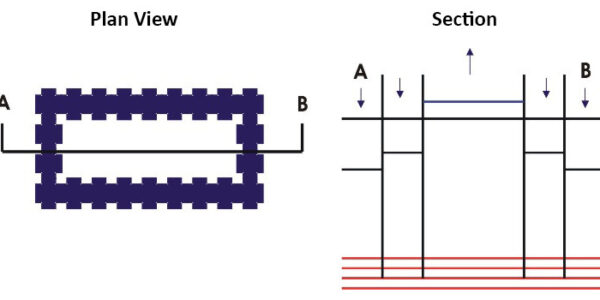
Figure 1 shows a schematic diagram of such a double-walled cell in which a hydraulic test was undertaken at Borden. The cell extended to a depth of 14.7 m through a surficial sand aquifer into an underlying aquitard.
The sealable cavities were injected with a bentonite slurry. For the test, the water level in the moat bounded by the two walls was maintained at a constant level. At the start of the test, the water level in the internal cell was raised by approximately 1 m relative to the natural water table in the vicinity of the cell.
As the test proceeded, the decline in water level in the internal cell was monitored with time. Corrections were made to these levels to account for losses by evaporation.
In applying an analytical solution to assist in interpretation of data, it was assumed that the underlying aquitard was impermeable and that all leakage from the internal cell occured laterally through the barrier wall. In reality, some vertical leakage into the underlying aquitard would have occured, so this assumption would result in an overestimation of the hydraulic conductivity of the barrier.
As shown in Figure 2, the bulk hydraulic conductivity of the cell wall was calculated to be 6 x 10⁻⁹ cm/sec. Similar tests in other cells, including those sealed with organic polymers, resulted in bulk hydraulic conductivities ranging from 10-8 to 10-10 cm/sec.
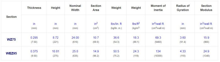
The Waterloo Barrier is available in two designs:
- Medium wall - WZ75
- Heavy wall - WEZ95
- ASTM A572 GR50
- CSA G40.21 GR 350W
- ASTM A6
- CSA G40.20
- GALVANIZED, ASTM A123, CSA G164
- COAL TAR EPOXY, SSPC-16
- FUSION BONDED EPOXY RESIN, ASTM A950
- BENDS CAN BE SUPPLIED TO ANY ANGLE
- `T` SECTIONS AND OTHER WELDED FABRICATIONS ARE AVAILABLE
- Deep, enclosing barriers at hazardous waste sites or municipal landfills to confine containment plumes and/or landfill gases
- Shallow, enclosing barriers to contain petroleum products or other light contaminants which float on the water table
- Isolation of contaminant hot spots by total enclosure or encapsulation
- Enclosures to control future groundwater contamination at new industrial or waste disposal sites
- Temporary barriers to facilitate removal or in-situ remediation of contaminants
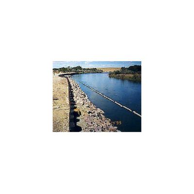
- Barriers along shorelines to prevent seepage of contaminated groundwater into waterways
- Funnelling or directing contaminant plumes to enhance the efficiency of pump-and-treat and in-situ remediation techniques
- Structural wall for excavation of contaminated soils
- Pilot scale remediation testing in contaminated aquifers under confined conditions
- Repair of leaking slurry walls
- Groundwater control in construction projects involving excavating and tunnelling
- Cofferdams
- Leakage protection for underground structures in high water table conditions