

- Home
- Companies
- Drexelbrook - AMETEK, Inc
- Products
- Impulse - Model TXXXX Series - Guided ...
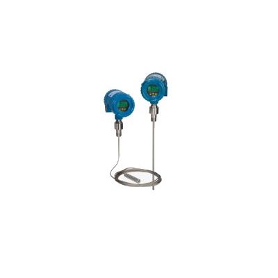
Impulse - Model TXXXX Series -Guided Wave Radar Meter
The Impulse Guided Wave Radar employs field proven TDR (Time Domain Reflectometry) technology to provide accurate measurement of Total Level, Distance or Volumetric outputs on all liquids and slurries. TDR Technology has been widely used for its inherent ability to remain unaffected by variations in the process materials electrical characteristics. AMETEK Drexelbrook has harnessed the technology with easy to use configuration menus in plain language. You will have the level measurement you need, configured within minutes.
Easy to install, Easy to use
-
Easy navigation
-
2-wire, HART or Modbus digital communication for Class I, Div. 1, Zone 0 installations
-
Push-Button configuration or HART communications
-
No calibration or Level changes needed
-
System configuration asks only those basic questions that pertain to your selected level measurement type, and in plain language. You will be expertly measuring the process level within minutes
-
Dual Compartment housing separates customer wiring terminals from the Intrinsically Safe electronic circuits, display and keypad
Dependable performance
- Sensor designs that will tame even the most difficult level measurement application
-
Despite disturbances such as agitated, or irregular surfaces, foam or coating of the probe, the Impulse Guided Wave TDR will continue to provide reliable and accurate measurements.
-
Unaffected by changes in density and dielectric properties, dusts, vapor, and turbulence
-
Low dielectric measurements down to a dielectric constant of 1.4, suitable for LPG/LNG service.
-
Hazardous approvals Intrinsically Safe, Explosion Proof and Non-Incendive approvals
Application versatility
- Probe Type and Material selections for all applications Ideal for level measurement of Liquids and Slurries.
-
Ideal for replacement of costly mechanical displacer systems
Input Power:
13 – 30 VDC, I.S. HART Version
14 - 30 VDC, X.P. HART Version
11-30 VDC, X.P. Modbus Version (400mw max at 12VDC)
Output Signals:
2-wire, 4-20 mA, HART (isolated)
Error Signals – 3.7 / 22 mA
User selectable or Digital Modbus
Modbus Communication
RTU or ASCII Mode
Baud rate up to 57,600
Multi Modbus data formats are available:
Integer, Long Integer, Floating Point, Enron, 16-bit, 32-bit, and more.
Maximum Loop Resistance:
Supply Voltage - 13 (I.S version) or - 14 (XP version) / 0.022 = max. loop resistance
Output Mode:
1 Output: Total Level, Distance or Volume
Measurement Range:
Flexible Cable sensors: 1 to 50 ft. (15 m)
Rod sensors: 1 to 12 ft. (3.6 m)
Coaxial sensor: 1 to 20 ft. (6 m)
Upper / Lower Dead Zones:
Sensor dependant
Sensor Types:
Single Rod, 5/16" (8 mm) OD
Single Cable, 5/32" (4 mm) OD
Single Cable, 5/16” (8 mm) OD
Double Rod, 1.2” (31 mm) OD assembly
Double cable, 1.2” (31 mm) OD assembly
Coaxial, 7/8” (22 mm) OD
Response Time:
Less than 1 second
Warm-up time:
Less than 60 seconds
Surge Protection:
1000 V power/signal to ground
Process Temperature (measured at the mounting):
-40 to +392°F (-40 to 200°C)
Process Pressure:
Vacuum to 580 psig (-1 to 40 bar)
Gasket Sealing Materials (options):
PEEK &: Viton, Kalrez 6375, EPDM
Display:
2-line, 7 digit, LCD Character height: 0.25” top line, 0.36” bottom line
UV Rated:
No Sunshield required
Accuracy:
K > 10: +/- 3 mm or 0.03% of measured distance, whichever is greater
K < 10: +/- 5 mm or 0.05% of measured distance, whichever is greater
Repeatability / Resolution:
2 mm
Operational Temperature Limits:
Transmitter: -40 to + 158°F (-40 to + 70°C)
Sensor: -40 to + 392°F (-40 to + 200°C)
Configuration:
Local Display with Keypad is Standard
HRTWin PC Software is available for HART Versions only
Signal Damping:
0 – 90 seconds
Electrical Enclosure:
Dual Compartment, Powder Coated
Aluminum to NEMA 4X, IP66
Electrical Connection:
¾” NPT, M20 X 1.5
Process Connections:
Thread: ¾” NPT, 1” NPT, 1-1/2” NPT, sensor dependant.
Flange: 1” ANSI through 8” ANSI, 150#, 300# ratings, others on request.