- Home
- Companies
- Thermtest Inc.
- Products
- Thermtest - Model HFM Series - Heat ...
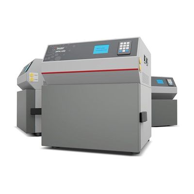
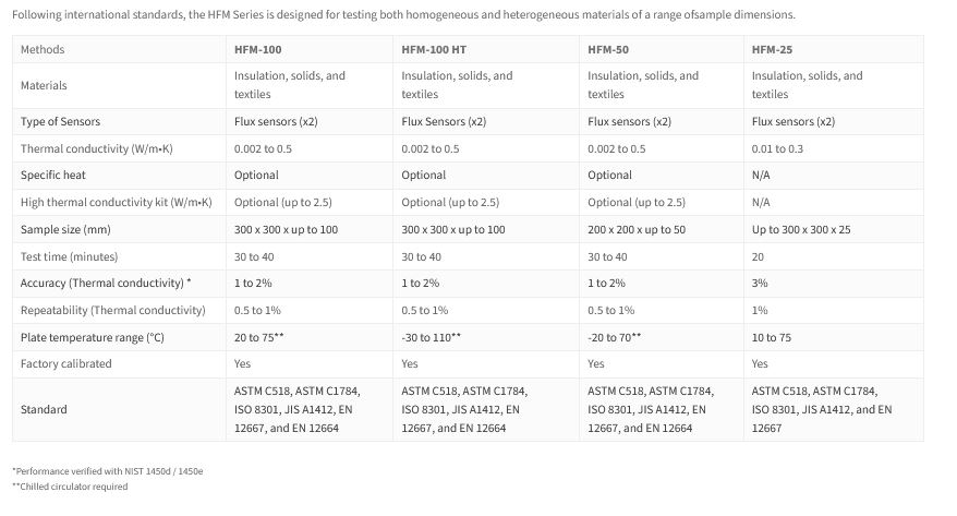
Thermtest - Model HFM Series -Heat Flow Meter
Heat flow meter for measuring the thermal conductivity and thermal resistance of insulation and construction materials.
The Heat Flow Meter is an easy-to-use technique for measuring the thermal resistance and thermal conductivity of insulation products, construction materials, packaging and assemblies. Thermal conductivity is the measurement of the ability of a material to conduct heat and can be critical for defining energy efficiency and thermal performance in materials. Our HFM series was designed and engineered to combine the highest accuracy, repeatability, widest temperature range and industry leading performance all at an exceptional value.
- Factory calibrated
- Two flux sensors with surface thermocouples for accurate measurement of thermal resistance and thermal conductivity
- Multiple Peltier heating / cooling plates for rapid control of temperature
- Thickness is measured to an accuracy of 0.05 mm (0.0019 in) with the use of four digital optical encoders
- Front panel operation allows full control of all HFM functions, or use the new feature packed HFM-100 / HFM-100 HT / HFM-50 Software for basic and additional functions, such as printing and exporting
- Plate clamping can be automated or set to a user defined thickness—ideal for compressible materials
- Follows international standards: ASTM C518, ASTM C1784, ISO 8301, JIS A1412, EN 12667, and EN 12664
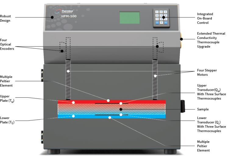
The second generation HFM-100 / HFM-100 HT / HFM-50 instruments are an excellent choice when making steady-state thermal conductivity measurements of specimens like insulation products and construction materials. We’ve rigorously engineered the Heat Flow Meter (HFM) to meet the requirements of international standards including ASTM C518, ASTM C1784, ISO 8301, JIS A1412, EN 12667 and EN 12664. Operating the HFM is straightforward—a sample is positioned between two heating and cooling plates. The upper plate, powered by stepper motors positioned in each corner, lowers to contact the top of the sample. Plate contact with the test specimen is controlled by a standard applied pressure, or by a user defined specimen thickness.
Stepper motors are controlled by individual optical encoders for the measurement of sample thickness (L), to the nearest 0.05 mm (0.0019 in). Integrated logic between stepper motors allows the upper plate to sense and adjust for specimens with surface variations, optimizing plate – specimen contact for measurements. One heat flux sensor is integrated into each plate, and is used to monitor heat flux (Q/A), generated due to the difference in temperature (ΔT) between the top and bottom plate at regular intervals, until steady-state heat flux is observed. The composite heat flux is then used to measure thermal resistance (R) and calculate thermal conductivity (λ) according to Fourier’s Law.