

- Home
- Companies
- IZAK Scientific
- Products
- IZAK Scientific - LED Color and ...
IZAK Scientific - LED Color and Position Tester System
The LED Color and Position Tester System is a specialized tool designed for evaluating the color uniformity and positional accuracy of LEDs. It is equipped with a high-resolution imager, specialized optics, and advanced software applications. The system is engineered for precise analysis of LED-based products and PCBs, making it suitable for manufacturers seeking rigorous quality assurance. It provides robust testing capabilities, ensuring accurate assessment and easy operation. The system includes an API enabling integration with other automated testers or functioning as a standalone application. Commands such as opening/closing the camera, learning configurations for different PCB types, and performing tests that log results in CSV files are included. Users can evaluate whether LED colors and configurations are correct and identify missing or disabled LEDs.
The LED Color and Position Tester System is an advanced tool equipped with a high-resolution imager and specialized optics, complemented by sophisticated software applications. This system is engineered for precise evaluation of LED color uniformity and positional accuracy. It offers robust testing capabilities, ensuring detailed analysis and quality assurance in LED based products and PCB. Ideal for manufacturers, this system combines accuracy with ease of use for optimal LED assessment.
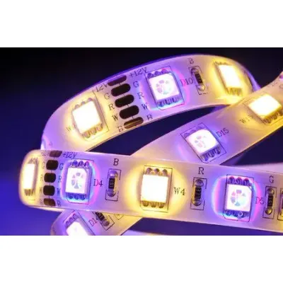
LED’s Color and Position Recognition System
The LED’s color and position systems were designed to detect LED colors and positions on PCB boards or indication bottoms on electronics.
Description
The system includes an imager with optics and software applications. The software application can be an API (DLL file) integrated into other automated testers or as a standalone tester application.
The API or application only has four commands:
Open/Close camera (can work with images instead of the camera)
Learning a new configuration: For example, one configuration for one type of PCB and another configuration for a different PCB type. Each PCB type (or other LED configuration) needs a specific configuration file after learning.
Test – assessing all LEDs that are currently operated and log results to a *.csv log file (see more information below).
The test command is executed without any GUI and provides Pass/Fail test results based on matching-grade criteria defined by the user. The system can indicate whether the colors and configuration are correct and locate missing or disabled LEDs.