
- Home
- Companies
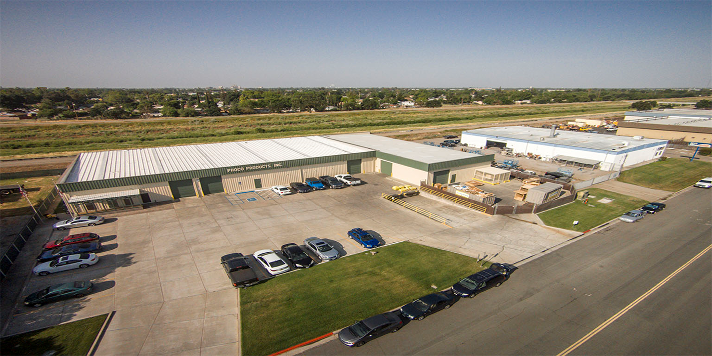
- Proco Products, Inc.
- Products
- Proco - Model Style 233L - Low-Profile ...
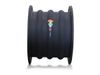
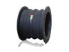
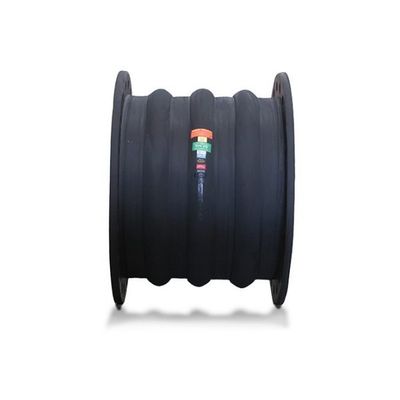
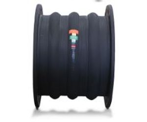
Proco - Model Style 233L -Low-Profile Triple-Arch Expansion Joints with Reinforcing Ring
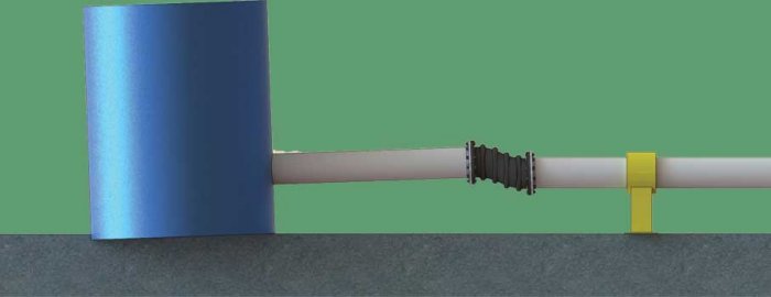
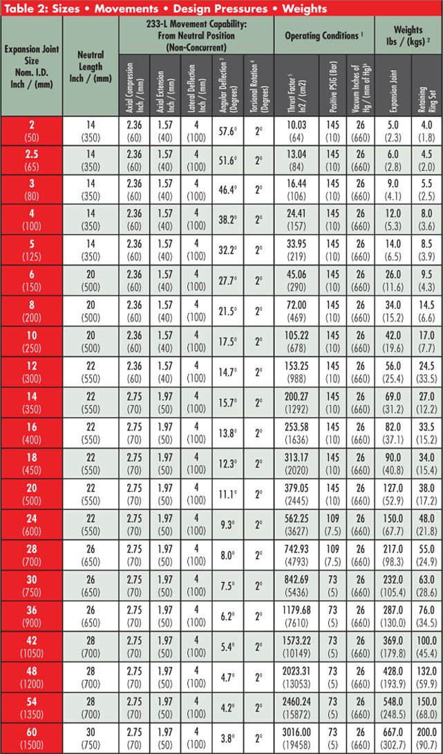
Proco Series 233L expansion joints are built to withstand even the most rigorous piping system configurations. They are low-profile, triple-arch products which are specifically designed to absorb directional movements of rigid pipe systems, as well as reduce noise and vibration, and compensate for misalignment due to long-term settling.
Some of the notable features and benefits of the Proco Series 233L are:
- Absorption of Directional Movement
- Absorption of Vibration, Noise and Shock
- Compensation for Misalignment
- Wide Range of Service and Lighter Weight
- Easy Material Identification
Absorbs Directional Movement
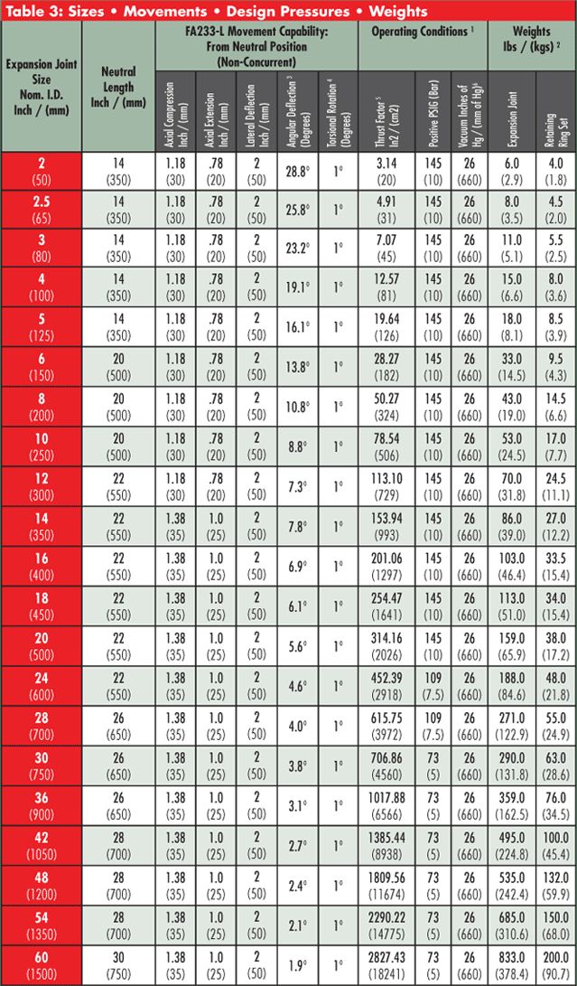
Thermal movements appear in any rigid pipe system due to temperature changes. The Style 233-L and 234-L low profile arch allows for axial compression or axial extension, lateral deflection as well as angular and torsional movements. (Note: Rated movements in this publication are based on one plane movements. Multiple movement conditions are based on a multiple movement calculation. Contact Proco for information when designing multiple pipe movements.)
Absorbs Vibration, Noise and Shock
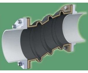
The Style 233-L and 234-L expansion joints are manufactured with the integral rubber flange joining the body at a true 90º angle. This ensures the product will install snug against the mating pipe flange free of voids creating less turbulence in the pipe system.
Compensates for Misalignment
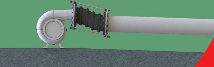
The Style 233-L and 234-L expansion joints are designed for large lateral movements due to long term settlement.
Wide Service Range and Less Weight
Engineered to operate up to 145 PSIG (nominal size dependent) or up to 250ºF (elastomer dependent), the Series 233-L and 234-L can be specified for a wide range of piping system requirements. The Series 233-L and 234-L rubber expansion joints are constructed in various elastomers with rubber impregnated polyester tire cord and a reinforcing ring at the top of the arch to provide stability in large lateral offset conditions.
Material Identification
All 233-L and 234-L expansion joints are strip branded with cure dates and elastomer designations.
Large Inventory
Proco Products, Inc. maintains one of the largest inventories of rubber expansion joints in the world.

Notes:
All Products are reinforced with Polyester Tire Cord
- Expansion Joint “Cover” can be coated with CSM UV Resistant Coating.
- All NN & NP elastomer designated joints meet the Coast Guard Requirements and conform to ASTM F 1123-87 and are marked accordingly.
- Branding Label will be marked as “Food Grade”.
- All elastomers above are not intended for steam service
NOTES:
- Pressure rating is based on 170˚ F operating temperature with a 4:1 safety factor. At higher temperatures, the pressure rating is reduced slightly. Hydrostatic testing at 1.5 times rated maximum catalog pressure or design working pressure of pipe system for 10 minutes is available upon request.
- Weights are approximate.
- The degree of angular movement is based on the maximum rated extension.
- Torsional movement is expressed when the expansion joint is at neutral length.
- Calculation of Thrust (Thrust Factor). When expansion joints are installed in the pipeline, the static portion of the thrust is calculated as a product of the area of the I.D. of the arch of the expansion joint times the maximum pressure (design, test or surge) that will occur in the line.The result is a force expressed in pounds.
- Take Design, surge or test pressure X thrust factor to calculate end thrust
- Parts listed at 26” Hg / 660 mm Hg vacuum have a design rating of 30” Hg / 762 mm Hg (full vacuum). Vacuum rating is based on neutral installed length, without external load. Products should not be installed “extended” on vacuum applications.
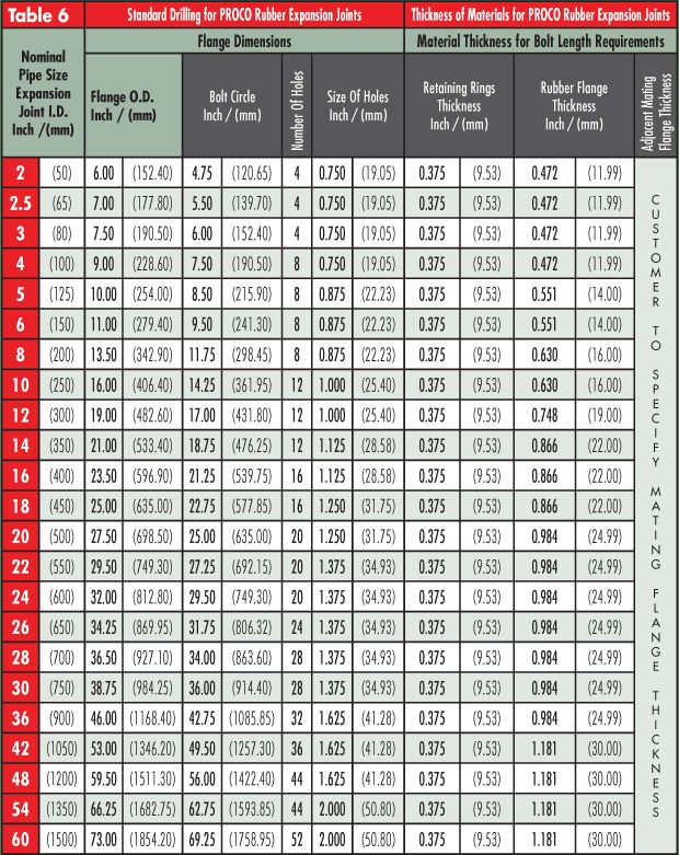
Metric Conversion Formula: Nominal I.D.: in. x 25 = mm; Dimensions/Thickness’: in. x 25.4 = mm.
Notes:
- Flange Dimensions shown are in accordance with ANSI B16.1 and ANSI B16.5 Class 125/150, AWWA C-207-07, Tbl 2 and 3 - Class D, Table 4 - Class E. Hole size shown is 1/8” larger than AWWA Standard.
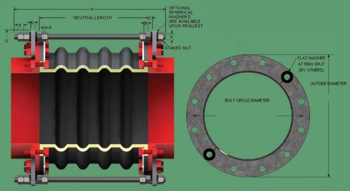
A - Retaining Ring Thickness.
B - Rubber Flange Thickness.
C - Adjacent Mating Flange Thickness (By Others).
D - Control Unit Plate Thickness.
E - Double Nut Thickness is determined by Control Rod Diameter.
F - Control Rod Bolt Length is determined by A through E + OAL 1.
G - Control Rod Plate O.D.
H - Maximum Rod Diameter.
1. Service Conditions:
Make sure the expansion joint rating for temperature, pressure, vacuum and movements match the system requirements. Contact the manufacturer for advice if the system requirements exceed those of the expansion joint selected. Check to make sure the elastomer selected is chemically compatible with the process fluid or gas.
2. Alignment:
Expansion joints are normally not designed to make up for piping misalignment errors. Piping should be lined up within 1/8”. Misalignment reduces the rated movements of the expansion joint and can induce severe stress and reduce service life. Pipe guides should be installed to keep the pipe aligned and to prevent undue displacement.
3. Anchoring:
Solid anchoring is required wherever the pipeline changes direction and expansion joints should be located as close as possible to anchor points. If piping is not adequately anchored, control rods should be used. If anchors are not used, pressure thrust may cause excessive movement damaging the expansion joint.
4. Pipe Support:
Piping must be supported by hangers or anchors so expansion joints do not carry any pipe weight.
5. Mating Flanges:
Install the expansion joint against the mating pipe flanges and install bolts so that the bolt head and washer are against the retaining rings. If washers are not used, flange leakage can result – particularly at the split in the retaining rings. Flange-to-flange dimension of the expansion joint must match the breech opening. Make sure the mating flanges are clean and are flat faced type or no more than 1/16” raised face type. Never install expansion joints that utilize split retaining rings next to wafer type check or butterfly valves. Serious damage can result to a rubber joint of this type unless installed against full face flanges.
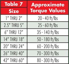
6. Bolting Torque:
Table 7 shows the recommended torque ranges for non-metallic expansion joints with full-faced rubber flanges: Torque specifications are approximate. Tighten bolts in stages using cross-bolt tightening pattern. If the joint has integral fabric and rubber flanges, the bolts should be tight enough to make the rubber flange OD bulge between the retaining rings and the mating flange. After installation, the system should be pressurized and examined to confirm a proper seal. Torque bolts sufficiently to assure leak-free operation at hydrostatic test pressure. Note: Torque values are approximate due to mating flange surfaces, installation offsets, operating pressures and environmental conditions.
7. Storage:
Ideal storage is in a warehouse with a relatively dry, cool location. Store flanges face down on a pallet or wooden platform. Do not store other heavy items on top of expansion joints. Ten year shelf life can be expected with ideal conditions. If storage must be outdoors, place on wooden platform and joints should not be in contact with the ground. Cover with a tarpaulin.
8. Large Joint Handling:
Do not lift with ropes or bars through the bolt holes. If lifting through the bore, use padding or a saddle to distribute the weight. Make sure cables or forklift tines do not contact the rubber. Do not let expansion joints sit vertically on the edges of the flanges for any period of time.
9. Additional Tips:
A. Do not insulate over a non-metallic expansion joint; however, if insulation is required, it should be made removable to permit easy access to the flanges. This facilitates periodic inspection of the tightness of the joint bolting.
B. It is acceptable (but not necessary) to lubricate the expansion joint flanges with a thin film of graphite dispersed in glycerin or water to ease disassembly at a later time.
C. Do not weld in the near vicinity of a non-metallic joint.
D. If expansion joints are to be installed underground, or will be submerged in water, contact manufacturer for specific recommendations.
E. If the expansion joint will be installed outdoors, make sure the cover material will withstand ozone, sunlight, etc.
F. Check the tightness of lead-free flanges two or three weeks after installation and retighten if necessary.
Warning: Expansion joints may operate in pipelines or equipment carrying fluids and/or gasses at elevated temperature and pressures and may transport hazardous materials. Precautions should be taken to protect personnel in the event of leakage or splash. Rubber joints should not be installed in areas where inspection is impossible. Make sure proper drainage is available in the event of leakage when operating personnel are not available.