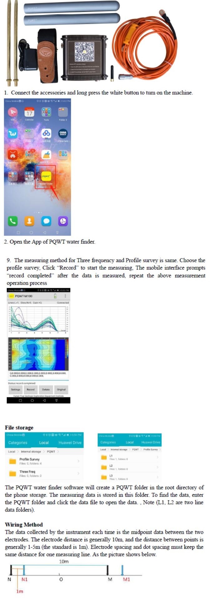

- Home
- Companies
- Sunmoy Technology Company Limited
- Products
- Sunmoy - Model PQWT-M100 & M200 & M400 ...
Sunmoy - Model PQWT-M100 & M200 & M400 -Mobile Water Detector
PQWT-M mobile water detector is based on the Earth`s electromagnetic field as the field source, based on the difference in the conductivity of different underground geological structures, and by studying the variation law of the electric field components at different frequencies to study the geological structure and changes, to find groundwater resources by scientific method.
Changes in geological structure are displayed in real-time through multiple curves.
Automatic form mapping geological profile by one key operate easily, get rid of complicated computer graphics. The site can quickly understand the geological structure through the automatic mapping curve and profile, and analyze specific information such as aquifers, fractures, faults, and caves.
The instrument is widely used in the rapid analysis of geological structure changes in different terrains such as plains, hills, mountains, plateaus, and basins to determine well locations, aquifers, and aquifer depth.
- No need to register
- No need network, no need traffic
- Automatically draw geological profile map
- Suitable for various terrain exploration
- Expert remote assistance to find location
- No experience person can operate in 5 minutes
- Two years warranty.
- Product model: PQWT-M100/200/400
- Measuring depth: 100/200/400 meters
- Measurement data unit: Electric field component of different frequencies of the earth electromagnetic field ?Vs(mV)
- Measuring range:
- 0mV-1000mV, the instrument automatically converts the range
- Measurement accuracy: 0.001mV
- Measuring channel: 4/6/8 channels
- Channel gain: 1-200,000 times
- Measurement frequency: 30/36/48 frequency
- Weight: 0.55kg (host)
- Power: The instrument uses 18650*2 3000mAh rechargeable lithium battery
- Display: LED indicator
- A/D conversion: 8-bit 1Msps
- Input impedance: ≥10MΩ
- Relative humidity: ≤85%
- Power consumption: About 1W
- Working environment temperature: -20?-+50?
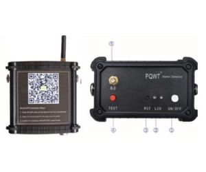
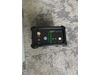
- ON OFF: Power switch button.
- LED light: The left side is the line indicator light (die light is not on during standby put the two copper electrodes together, press the "TEST" line detection button, if the green light is on indicates that the line is normal, the green light is off indicate the line is fault): On the right is the power indication light. When the power is turned on. The blue light flashes indicating that the system is running. The fast flashing light indicates that the survey data is being sampled. The steady light indicates the system is broken down
- RST: System Reset burton
- TEST: Line test
- Antenna interface