

- Home
- Companies
- Promag Enviro Systems Ltd.
- Products
- Model 1248 - Dosing Siphon, Fluid ...
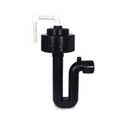
Model 1248 -Dosing Siphon, Fluid Dynamics
Improving System Performace With Automatic Siphons What the Siphon Does The automatic siphon system stores liquid in a tank until a certain elevation of the liquid is reached (the high water line), then the siphon automatically comes into operation and rapidly drains the tank to the low water line. When the low water line is reached, the siphon shuts off and stops the flow of liquid.
All liquid coming into the tank will again be stored until the high water line is reached and the siphon repeats the cycle. This is accomplished with no moving parts. The siphon operates on the hydraulic force of the liquid rising in the dosing tank.
Fluid Dynamics Siphons provide automatic siphons in many different sizes and drawing depths. We can also provide dual, triple, and quadruple siphon systems. In short, we have the siphon to meet the needs of your specific system. Please read below for further information.
Introduction
The septic tank-soil absorption sewage disposal system continues to be an important method of sewage disposal for singe family homes, clusters of homes and small communities throughout the the world. Since no practical substitute for this essential type of disposal system has been developed, the public interest can best be served by an important in soil absorption system performance.
The Problem
The leaching field is the part of the septic tank disposal system most prone to failure. Failure is characterized by a decline in the ability of the soil to accept tank effluent at the design rate. This leads to underground pounding and crusting, which in turn leads to liquid breaking through to the surface of the ground.
The Solution
As many engineering studies* and extensive field tests indicate, continuous discharge from the septic tank should be avoided. Continuous discharge causes the distribution to be limited to a few areas within the absorption field resulting in an overloading of the infiltrative surface in these areas. In order to maintain the infiltrative capacity of the soil, alternate periods of loading and resting of the leaching system should be provided. An inexpensive and trouble-free method of achieving this solution is by using a dosig tank together with an Automatic Dosing Siphon.
*"A Study of Methods of Preventing Failure of Septic Tank Percolation System" Sanitary Engineering Research Laboratory, University of California, Berkeley.
"Dosing and Resting To Improve Soil Absorption Beds" American Society of Agricultural Engineers, Paper #73-256
Alternating Siphons
Even longer periods of rest can be achieved by installing two siphons in the dosing tank; the siphons alternately discharge the liquid out of the tank into one-half of the field at a time. This is possible because the siphons are installed in one tank (see attached document for explanation).
Applications
The primary use of the Automatic Siphon is to dose leach fields, sand filters, and other soil absorption systems. They may also be used to maintain minimum water velocities to insure proper scouring action of the liquid in the pipe lines. Alternating siphons are frequently used to direct effluent flow to different locations.
Materials of Construction
The Fluid Dynamic Automatic Siphon is manufactured from chemical resistant materials which are unaffected by the fluids found in domestic sewage. They are immune to sewer gases and the sulfuric acid generated by completion of the hydrogen sulfide cycle.
The siphon traps and bells are molded, one piece each, from black high density polyethylene. The vent piping is constructed from schedule 40 PV pipe and fittings. The bolts are stainless steel.
Determining the Volume of Liquid Dosed by the Siphon
The volume of liquid dosed by the siphon is a funtion of the area of the tank and the drawing depth of the siphon.
Example 1: To figure the volume of dose of a Model 417 siphon (17" draw depth) placed in a rectangular tank with inside dimensions of 4` x 5`:
Step 1, Figure the area of the tank in square inches, 48"x60"=2880 inch squared
Step 2, Figure the volume in cubic inches (The draw down of the siphon x the area of the tank), 17x2880=48,960 inch cubed
Step 3, Convert to cubic feet (divide by 1728),
48,960/1728=28.33 feet cubed
Step 4, Convert cubic feet to gallons (there are approximately 7.48 gallons in a cubic foot), 28.33x7.48=211.93 gallons
- Model: 1248
- Siphon Diameter: 12”
- Draft Size: 48”
- Average discharge rate: 2000 GPM
- Field Dosing Siphon System