

- Home
- Companies
- Eureka Pumps AS
- Products
- Model API 610 - Cargo Pump
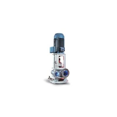
Model API 610 -Cargo Pump
The Eureka cargo system includes cargo pumps with driver, automatic stripping system, ballast pumps with driver, stripping pump with driver, tank sea water wash pump with driver and a separate Eureka controller to monitor and control the whole system during a safe and optimized operation.
The Eureka cargo pumps is a vertical or horizontal pump with fixed speed or variable speed drive. To change speed during operation either a hydraulic coupling or frequency converter is used. Normally the motor and the pump is located in two separate rooms and a gas tight transmission is required. The pumps can be fitted with a priming unit on the suction side of each pump.
To ensure robust operation and prevent hydrocarbon gas to the atmosphere the pump include an API 682 pressurized mechanical seal arrangement.
The cargo pumps are used to unload crude oil from the cargo tanks onboard the FPSO to an adjacent crude oil tanker connected through a fiscal metering package and flexible unloading hose reel system. The pumps NPSH available are decreasing as the tank level is lowered during unloading. The pump speed must thus be decreased in several steps at low tank levels to ensure that the pump NPSH required are lower than NPSH available from the system and eliminate pump cavitation.
The pumps are mainly arranged in 3 x 50% or in 4×33% configuration with parallel operation. Hence, two or three pumps will typically operate while one of the pumps will typically be in stand-by.
The API 610 EUREKA BB2 pump is a, single stage, double suction, double volute, radially split API 610 pump. It is designed for continuous duty and is particularly adaptable for offshore, oil refinery, chemical plant and other industrial services pumping fluids under a wide range of temperatures and pressures. It is available both in vertical and horizontal execution.
Case and Cover
The pump is radially split and the suction and discharge nozzles are cast integral with the case. The case is of double volute design, which gives very low radial force from zero to maximum capacity. This minimises shaft deflection, wearing ring wear, seal, shaft sleeve wear, and probability of bearing failure.
The drive end cover contains the seal chamber while the non drive end cover contains the silicon carbide bearing.
Sturdy mounting ribs are integrally cast with the casing and pipe nozzles – creating the closest transfer of nozzle forces to pump foundations.
In vertical version, the pump foundation and motor pedestal are directly bolted to the mounting ribs, making an integrated total structure.
In horizontal version the foundation pedestals are directly bolted to the same mounting ribs.
Piping
The standard pump is furnished with case drain, seal flushing and volute vent. Other connections are available at extra cost.
Flanges
Suction and discharge nozzles are standard furnished with 300 lbs ANSI B16.5 flanges with 1/16″ raised face.
Pumps can be furnished with other flange ratings and facing upon request.
For the vertical version the nozzles are either arranged in-line or side by side.
For the horizontal version, the nozzles are arranged as top top or side side.
Seal chamber
The API 610 EUREKA BB2 pumps have only one seal chamber, as the non drive shaft end does not need to penetrate the cover. The seal chamber is extra deep to provide ample space for installation of dual mechanical seal.
Shaft
The shaft is of ample size to transmit the required power and to prevent excessive deflection and is machined and ground to required dimensions.
Impeller
The impeller is double suction and designed with a large eye area to ensure low NPSH requirements and thus reduce the possibility of cavitation.
Impeller wear rings
The impeller wear rings are mounted on the impeller with a slight shrink fit and pinned in position.
Cover wear rings
The case wear rings and cover wear rings are inserted in the case and cover with a slight interference fit and secured with a hollow head sets crew.
Throat bushing
When a throat bushing is required, it is inserted in the cover with a slight interference fit and secured with a retaining ring.
Shaft sleeve
Shaft sleeves are keyed to prevent rotation and axially secured between impeller and impeller lock nut
Gaskets
O-ring type gaskets are provided between the case and the covers, which allow metal to metal assembly of the case and covers.
Bearings
The pump is equipped with an oil-lubricated antifriction or tilting pad bearing to take thrust and radial forces at the drive end. At the non-drive end the shaft is equipped with a silicon carbide journal bearing, flushed and lubricated by the pumped medium. This eliminates the need to let the non drive shaft end penetrate the cover.
As an option, the vertical version can be equipped with external oil lubricated bearing in the non drive end.
Coupling
Each pump is furnished with a spacer type flexible coupling and designed for easy mounting/dismounting. The bearing and mechanical seal may be changed at site without dismounting the electric motor.
The double seal system with barrier fluid system is used for pumping hazardous liquids, typically hydrocarbon cargo offloading applications.
The seal system complies with API 682 Plan 53A. Pressurized external barrier fluid reservoir supplying clean fluid to the seal chamber. Circulation is by an internal pumping ring. Barrier fluid pressure is greater than pump discharge pressure, ref.
API 682 seal arrangement no. 3.
Designed according to API 610 requirement
- Pump design according to API 610 in all material combinations
- 10 years maintenance intervals
- High pressure solutions
- Multiple API610 nozzle forces
- Low NPSHR to prevent cavitation
- Variable speed design