

Model Three-arm Pendulum -Experimental Control System
The three-arm pendulum is used for practical implementation and scientific investigation of control concepts and as a laboratory experiment in teaching. The three-arm pendulum is an experimental setup with a linearly movable carriage or slide on which up to three freely swinging pendulum arms can be mounted. The objectives that can be impressively demonstrated with the aid of the three-arm pendulum include reaching one of the unstable rest positions of the pendulum and quickly approaching the stable rest position. For this purpose, the only manipulated variables available are the travel speed of the carriage and, as measured variables, the carriage position and the arm angles.
Core tasks of the three-arm pendulum are:
-
analytical and experimental system modeling
-
design of state controllers for non-linear systems
-
observer design
-
trajectory drive
The high manufacturing quality and the selection of high-quality components of the three-arm pendulum ensure that the highly dynamic setup meets the high demands on the mechanics, the sensors and actuators as well as the computer technology. The three-arm pendulum is characterized by precise travel, minimal backlash and very low slip of the moving components.
The pendulum is controlled via the real-time capable development system dSPACE MicroLabBox, which comes with the associated Matlab/Simulink toolbox for developing the software.
-
Sturdy construction 4650mm (length) x 1360mm (height) x 530 mm (frame dimensions)
-
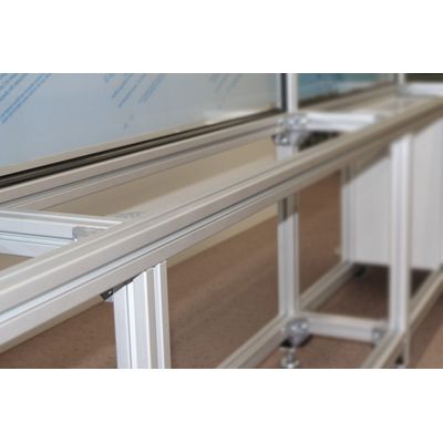
Aluminum profiles with granite support
-
Required installation space 4750mm x 2600mm x 710mm
-
Linear rail with a travel of approx. 1600 mm
-
Trolley with coupling to the pendulum
-
Weight approx. 130 kg
-
Servocontroller, power supply, mains filter, logic operations, and signal adaptation for connection to dSPACE MicroLabBox in the control cabinet (adaptation to other control is possible)
-
Maximum motion is electrically limited by safety limit switches even in the event of software or inverter errors, and secured by shock absorbers.
-
Error memory and cycle monitoring of the higher-level control by hardware with forced shutdown
-
Drive of the carriage by a servo motor (of approx. 1 kW). The carriage position is measured by a sensor on the axis of the motor with 1024 pulses/revolution (70 mm travel)
-
Power supply of the pendulum arms by accumulators/ and (charging by supplied charger)
-
Resolution of the pendulum axes 2048 pulses per revolution
-
Serial IR data transmission through the hollow shafts of carriage and arm 1
-
Reference switch for detection of absolute carriage position for defined starting point of experiment
-
Limit switch for maximum travel