- Home
- Companies
- McWane Ductile - A Division of McWane, ...
- Products
- TR Flex - Restrained Joint Pipe
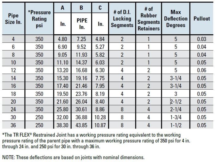
TR Flex - Restrained Joint Pipe
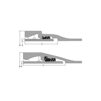
Simply put, the most-widely accepted and installed integrally-cast restraint joint system in the ductile iron pipe industry. Proven as a versatile and easy-to-use item, this joint is flexible, sure, and watertight to and beyond its 350-psi pressure rating while preventing longitudinal separation of the joints whether installed above or below ground. TR Flex utilizes the Tyton joint gasket for a watertight seal along with a factory adapted spigot and extended bell casting to provide positive and permanent joint restraint.
Step 1. (4”– 10”) Lay pipe such that one of the bell slots is accessible. (12”– 20”) Lay pipe such that both of the bell slots are accessible, in the horizontal position if possible. (24”– 36”) Lay pipe such that all four of the bell slots are accessible, in the diagonal position if possible.
Step 2. Clean the bell socket and insert gasket.
Step 3. Clean the spigot end to the assembly stripes.
Step 4. Lubricate the exposed surface of the gasket and pipe spigot end back to the weld bead.
Step 5. Make a normal push-on joint assembly, completely homing the pipe until the first assembly strip is in the bell socket. Keeping the joint in straight alignment during the assembly process.
Step 6. (4”– 10”) Insert the right-hand locking segment into a bell slot and slide the segment clockwise around the pipe. (12”– 36”) Insert lower locking segment into a bell slot and slide the segment around the pipe.
Step 7. (4”– 10”) Insert left-hand locking segment into the bell slot and slide the segment counter-clockwise around the pipe. (12”– 36”) Insert upper locking segment into the same bell slot and rotate around the pipe.
Step 8. (4”– 10”) Hold the segments apart and wedge the rubber retainer into the slot between the two locking segments. (12”– 36”) Hold the upper segment in place and wedge the rubber retainer into the slot between the two locking segments.
Step 9. (4”– 10”) None. (12”– 20”) Repeat steps 6–8 for other slot. Make sure that all 4 locking segments and 2 rubber retainers are securely in place. (24”– 36”) Repeat steps 6–8 for other slot. Make sure that all 8 locking segments and 4 rubber retainers are securely in place.
Step 10. Extend the joint to remove the slack in the locking segment cavity. Joint extension is necessary to attain the marked laying length on the pipe and to minimize growth or extension of the line as it is pressurized.
Step 11. Set the joint deflection as required.