

Scanning Radio Telemetry
The RDNET2000TM Scanning Radio Telemetry System has been designed to deliver simple but effective real-time communications of digital control and alarm signals over an area from a few square km to hundreds of square** km at a fraction of the cost of installing and operating private wire data links and with substantially improved reliability in areas prone to storms.
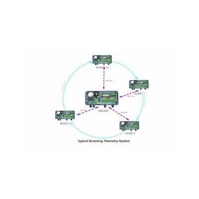
System comprise typically of a single central Radio Telemetry Master station and between 1 and 8 Radio Telemetry Outstation often referred to as Slaves.
Scanning Radio Telemetry – How it works
The Scanning Telemetry Radio Master Station emits what is called a poll message to each of the Outstations (slaves) in sequence. The poll message contains the address of the Slave and data from the Master to that Slave wrapped up in what is called a packed, terminated in a 16-bit error check message called a cyclic redundancy check, often abbreviated to CRC16. The Slave upon receipt of the message verifies the address, the CRC16 and if both are correct applies any updates to its outputs as commanded by the Master. The Slave then reads the status of its own input/s and then delivers a reply telegram back to the Master.
Upon receipt of the reply from the Slave, often termed the acknowledgement or ACK for short, the Master then updates the outputs relating to that particular Slave before moving on to the next Slave following what is called the scanning or poll sequence.
In the unlikely event that the ACK is not received by the Master, the Master automatically halts the scanning/poll sequence and re-broadcasts the request to the Slave. If after a second and then third attempt the ACK is not received the Master will raise an alarm to warn of issues with that particular Slave before re-commencing the scanning sequence and talking to the next Slave until the cycle is complete. Once scan cycle is complete the Master start the scan cycle all over again giving any failed Slave a second chance to re-join the system.
RDNET2000 Scanning Radio Telemetry System
The system as been scaled to command anything from between 1 and 8 slaves, each of which has a fixed input/output capacity of digital inputs and 4-digital outputs.
If more digital inputs or outputs are required at a single location the capacity of any un-used slaves can be assigned to that particular location.
General Specification:
MASTER STATIONS
- Master Station Controller Card:
- 230V AC linear power supply, 5A 12V dc with 13.6V leads acid battery float charger:
- Sequence Controller for 1 – 8 Slave
Master Station Radio
- 1mW to 5W Licensed or Un-Licensed options
- VHF 150MHz to 490MHz available to order
- 12.5KHz or 25KHz Channels
- MPT1328, MPT1329, MPT1411
- EN300-220-1, EN300-113
- Typically -115dBm sensitivity
I/O Cards Master
- 4 x digital inputs optically isolated to > 1Kv
- 4 x input status LEDs
- 4 x relay outputs isolated to > 1KV
- 5A 25V ac
- 4 x Output status LEDs
Slave Signal Monitor Cards
- 4 x relay outputs isolated to > 1KV
- 5A 25V ac
- 4 x Slave Status LEDs
Enclosure:
- Custom supplied to hold the number of cards
- 20mm cable gland / conduit entries
- N-type antenna connector
RADIO TELEMETRY SLAVE STATIONS
Slave Station Controller Card:
- 230V AC linear power supply, 5A 12V dc with 13.6V leads acid battery float charger:
- Signal Monitor output card
Slave Station Radio
- 1mW to 5W Licensed or Un-Licensed options
- VHF 150MHz to 490MHz available to order
- 12.5KHz or 25KHz Channels
- MPT1328, MPT1329, MPT1411
- EN300-220-1, EN300-113
- Typically -115dBm sensitivity
I/O Cards Salve/s
- 4 x digital inputs optically isolated to > 1Kv
- 4 x input status LEDs
- 4 x relay outputs isolated to > 1KV
- 5A 25V ac
- 4 x Output status LEDs
- Die Cast Aluminium 222mm x 360mm to 110mm
- IP 65
- 20mm cable gland / conduit entries
- N-type antenna connector