

Seperator
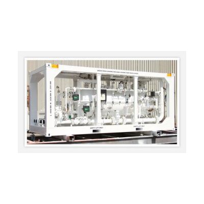
1440psi 42” x 10ft Horizontal 3 phase Well test Separator, H2S / CO2 service mounted in skid and covered crash frame with explosion proof lighting and supply cable on skid. 3”206F Inlet, 3”206M and 4”206M outlets and bypass manifold to Oil and Gas with 3” and 4” (Gas) ANSI 600 Full bore ball valves. Measuring equipment consists of 6” Daniel orifice meter and Barton static / differential recorder on Gas line. 2” and 1” Cameron Nu-Flo turbine meters with electronic readout on Oil lines and 1” Cameron Nu-Flo turbine meter on Water line. Shrinkage tester included.
Full set of orifice plates provided from 0.5 to 4.50” with set of Teflon gaskets and grease sticks.
Provision has been made for easy add on of electronic data acquisition system on Inlet, vessel and Gas, Oil and Water metering outlets.
Pneumatic Control equipment consists of 3” Pressure controller on Gas line, 3” Level controller on Oil line and 2” Level controller on Water line with transparent type Oil and Water sight glasses.
Nozzles are available on vessel for Pressure and Level alarm and shutdown systems.
Sample points are available for PVT Oil and Gas sampling. There is also a sample point on the vertical section of the Gas line for Isokinetic sampling.
There are two Pilot operated Pressure safety valves directly mounted on independent vessel nozzles.
Operating temperature range of -29 to 121 Deg C
General Specifications
- Well Test Seperator: 42” x 10ft x 1440psi in Skid and Crash Frame
- Nominal Vessel Size: 42” x 10ft Horizontal
- Design Pressure: 1440psi @ 122 Deg F
- Maximum Working Pressure: 1330psi @ 250 Deg F
- Service conditions: H2S / CO2
- Maximum Liquid rate (High liquid level): 15,000 BPD
- Maximum Gas rate (Low liquid level): 75 MMScfd
- Maximum Gross Mass: 16,000 kgs (14,000Kgs Tare weight with vessel empty)
- Dimensions: 6.058mts x 2.438mts x 2.591mts ( L x B x H)
- Fluid Inlet: 4” ANSI 600RF flange and 3”206 Female
- Fluid outlets
- Gas: 4” ANSI 600RF flange and 3”206 Male
- Oil: 3” ANSI 600RF flange and 3”206 Male
- Water: 2” ANSI 600RF flange and 3”206 Male
- Vent: 4” ANSI 150RF flange and 4”206 Male
Measuring equipment
Gas:
- 6” DC Daniel Orifice meter with 5.761” LB
- Barton 3 pen Pressure, Differential & Temperature recorder
- PVT sampling points including 1”NPTF for Isokinetic sampling
Oil:
- 2” & 1” Nu-Flo Turbine meters with MCII+ display
- Pressure, Temperature, PVT sampling points
- Calibrated Shrinkage tester
Water:
- 1” Nu-Flo Turbine meter with MCII+ display
- Pressure, temperature, Sampling points
Control equipment
- Gas: 3” FO pneumatic Pressure control valve with C1 Pressure controller
- Oil: 3” FC pneumatic Level control valve with L3 Level controller with external displacer and Sight glass
- Water: 2” FC pneumatic Level control valve with L3 Level interface controller with external displacer and Sight glass
- Safety devices:
- 2 x 3” x 4” Pilot operated Pressure Safety Valves mounted directly on independent vessel nozzles with 4” Vent line to skid edge
- 2 x Grounding points on opposite diagonal sides of base skid
- Manufacturing / Design Codes: ASME VIII Div.1 & U stamp / ANSI B.31.3 / NACE MR01.75