
- Home
- Companies
- Rocscience
- Software
- Examine - 3D Engineering Analysis for ...


Examine - 3D Engineering Analysis for Underground Excavations
Examine consists of three program modules: Model generates the geometry and boundary element discretization for underground openings, Compute performs the computation of stresses and displacements, using the direct boundary element method and Interpret, with 3D animation capability, visualizes the analysis results. Each of the three modules can be run independently. For example, the input data for Compute can be generated using Model or some other CAD based program. Similarly, Interpret accepts data from Compute or from some other source. Both Model and Interpret are fully interactive and menu-driven programs.
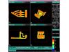
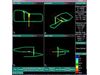
Examine consists of three program modules: Model, Compute and Interpret. Model is used to create the excavation geometry and boundary element mesh, and define material properties and loading conditions. Model geometry can be imported from AutoCAD or created in Examine using powerful CAD-based drawing and editing tools. Advanced mesh generation options simplify the task of generating a high quality mesh. The mesh is automatically checked for validity, to ensure that there are no gaps in the mesh and that elements do not intersect or overlap.
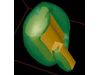
Examine uses the direct boundary element method to Compute the 3-dimensional elastic stress state around underground excavations. Stress, displacement and strength factor are computed at user-defined locations, including planes, volumetric grids, points, or on the excavation surface. The compute engine is optimized for speed and accuracy.
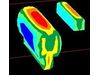
The Interpret module of Examine is used to visualize analysis results. Contouring, isosurface generation, stress flow ribbons and trajectories can be viewed. Advanced shading, transparency and animation algorithms provide state of the art graphical output. In addition to stress analysis, Examine can be used for a variety of other data visualization purposes. For example, Examine can be used to visualize micro-seismic datasets such as seismic velocity, source parameters, and event density.
- graphical data entry / editing
- B-REP – geometry construction using skinning, extrusions, facing
- Autocad DXF import / export
- automatic meshing / re-meshing techniques
- volume and surface area calculation
- automatic geometry validation
- distance measuring
- pressure boundary conditions
- geometry slicer
- constant, linear, or quadratic element formulations
- closed-form integration close to boundary
- conforming elements
- virtual number of elements
- free surfaces
- constant
- gravitational
- Hoek-Brown
- Mohr-Coulomb
- direct boundary element method
- optimized for speed and accuracy
- restart capabilities
- on cutting planes
- within volumetric grids
- at user specified points
- on surface of excavation
- isosurface generation
- stress trajectories
- stress flow ribbons
- stress / displacement / strength contours
- ubiquitous joints
- advanced rendering capabilities –
- Gouraud / Phong shading
- texture mapping
- smooth animation
- transparency
- display seismic / general data
- show stresses on surface of excavation
- differential stress between stages
- plot any function of stress, displacement
- scattered data interpretation
- GIF, PCX, TGA image files
- postscript printer support
- DxfGeo
- DStress
- Energy balance
- Eden
- AvgTen
- Convert to PTS
- Sphere
- Restart
- Tunnels
- Mining
- Excavations
- Rock