

- Home
- Companies
- Flite Software NI Ltd
- Software
- Liquids, Incompressible Flow System
Liquids, Incompressible Flow System
Delivers fast and accurate designs for Newtonian fluids. Determines system operating pressures, flow distribution and fluid physical properties. Allows for the modeling of a wide range of line equipment items.
FluidFlow solves the fundamental conservation equations of mass, energy, and momentum. Users can choose from three pipe pressure loss models as follows; 1) Moody (Darcy-Weisbach), 2) Hazen Williams or 3) Fixed Friction Factor (Darcy).
Comprehensive Fluid and Equipment Databases
Comprehensive databases of over 1200 fluids and over 800 equipment components included as standard. Databases are used extensively in FluidFlow in order to reduce the volume of data entry.
New fluids (including petroleum fractions), fluid mixtures and components can be quickly and easily added.
Databases that describe the performance and limits of fluid equipment items
Library of pipe materials, insulation materials and soil types for buried pipe calculations.
Database of manufacturers, costs, and user-defined areas of application.
Automatic Equipment Sizing Technology
Powerful Automatic Equipment Sizing technology included. FluidFlow will propose the most economical pipe size based on physical property data, capital equipment cost and energy costs.
Automatically size relief valves and bursting disks to ISO and API standards.
Pumps can be automatically sized based on either a design flow rate or design pressure rise across the system.
Automatically size pipes or ducts based on any of the following three methods; 1) Economic Velocity, 2) By Velocity and 3) By Pressure Gradient.
Heat Transfer Functionality Included
FluidFlow includes heat transfer functionality on all modules. Engineers can study heat transfer effects at heat exchangers, pipes and junctions. FluidFlow can model shell and tube exchangers, plate exchangers, coils and autoclaves.
Choose from a range of heat transfer options:
Buried pipe calculations.
Pipe heat loss/gain calculation.
Fixed heat transfer rate.
Fixed temperature change.
Ignore heat loss/gain.
Dynamic Analysis
Scripting allows the user to perform dynamic analysis on a model. These time-dependent simulations allow investigation into tank fill/drain times, system pressure as demands vary, control philosophies, and more.
Scripting can be used to perform a wide range of dynamic simulations including:
Analyse system pressure as demands vary.
Investigate system control philosophies.
Evaluate valve performance for variable speed pumps.
Flare stack depressurisation.
Optimise pump and system performance.
Analyse scale build-up in systems and study the effect on flow rate.
Design
Take a complete system modelling approach, considering the interaction and effect of connected pipes and fittings.
Comprehensive fluid and component databases enable rapid model development.
Perform both steady-state and dynamic simulations of piping systems. Choose from a number of pipe friction loss methods including Moody, Hazen-Williams, Fixed Friction Factor and Shell-MIT.
Analyse
Evaluate pump performance, identify energy savings opportunities and increase equipment reliability.
Determine system operating pressures, flow distribution, control valve performance (Calculated Cv & % open), and fluid physical properties throughout the model.
Consider what-if scenarios, evaluate system performance under varying operating conditions and propose design alternative quickly.
Size
Powerful equipment-sizing technology included – size pipes, pumps, control valves, orifice plates and safety relief devices (API and ISO standards).
Avoid unnecessary over-sizing of pipework and equipment by accurately determining actual system performance characteristics.
Consider limitations of existing systems and evaluate re-sizing of pipe sections to determine improvement opportunities.
Rationalise system capital and operational costs through optimised system performance and correct sizing of piping and fittings.
Communicate
Fully customisable reports allow for effective communication to colleagues, clients and peer review.
Customise flowsheet to visually communicate key results and design information.
Get feedback from colleagues or customers on key decisions, make design changes and evaluate results in real time.
Develop a clear and transparent design audit trail, meaning that personnel may change, but there is always a record of what was designed at that time.
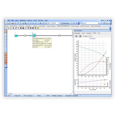
1. Vendor Pump Performance Curves:
This example shows the performance curves for a vendor pump on the left-hand side. This pump data was then modeled in a sample test-case system in FluidFlow.
When using FluidFlow, we can see where the system curve intersects the pump capacity curve and the actual duty-point on the performance curves. The calculated results for the pump allow us to see the operating efficiency, NPSHa, NPSHr as well as the duty head requirement.
2. Closed Loop Systems:
This example is of an existing purified water loop system modelled in FluidFlow which contains a single circulation pump which provided a maximum flow rate of 56 m3/h at 8 bar pressure. The general operating demand was 40 m3/h at 8 bar pressure. The total length of the piping is approximately 246 M with a rise of approximately 25.0 M on the return leg to the tank.
3. Liquid Modeling of a LNG Storage Delivery System:
This example shows the main take-off line for tanker loading from a LNG storage tank facility.
FluidFlow solves continuity, momentum and energy equations iteratively to arrive at an accurate solution. Phase states and physical properties are calculated at each point in the network. Solutions are valid for all flow regimes.
In this system, FluidFlow was used to design and model the liquid and vapor lines, including compressor plant.