
- Home
- Companies
- Geotechnical Engineering Modelling ...
- Software
- GEMS - Offshore Pile Foundation ...
GEMS - Offshore Pile Foundation Geotechnical Software
Commonly adopted offshore platforms are of jacket type and are mostly supported by pile foundations. The pile foundation designed for these structures should safely transmit the loads through the sub soil strata beneath the sea bed. The design of the foundation should meet the serviceability and safety requirements under operational and severe storm conditions.
The main types of load to which the piles are subjected to are the axial compressive, tensile loads, lateral loads and moments.
The ‘Offshore Pile Foundation Analysis’ suite of GEMS provides easy-to-use program modules for the all the above analysis. There are three modules available
The ultimate axial capacity under compressive or tensile load is computed based on the soil layer properties. The software gives the pile capacity at various depths of soil and also breaks it down to its contributing factors viz. shaft friction and base capacity. Different codes and practices can be used in the calculation of pile capacity. For clay and sand layers, API-2000 RP or API-2011 RP-GEO is followed with features to include user prescribed parameters. A distance of 3D is used for developing full base resistance in strong layers. A safe distance of from pile tip of 3D is adopted to preclude punch through underlying weak layers. For rock layers an approach based on unconfined strength is adopted.
This module has two independent sub modules:
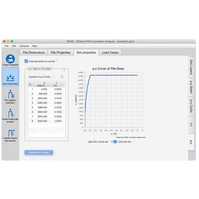
(a) Generation of t-z and q-z curves
Development of a set of t-z curves along the shaft length and q-z curve at the pile base for compressive loading. Multiple t-z curves are generated for each soil layer. The curves can be based on ‘API-2000 RP’ or ‘API-2011 RP GEO’ for sand and clay layers. This also takes into account the remoulded strength reduction factor R beyond post peak adhesion in clay layers. This sub-module is also available with Pile capacity estimation.
(b) Axial pile deformation analysis
Interaction between pile and soil is implemented by finite element modelling of pile as an elastic structural member of variable axial rigidity, soil support along pile shaft by a set of t-z springs and the base support is a q-z spring. Both t-z and q-z springs represented by curves, model the non-linear nature of soil support. Either user defined t-z, q-z data or curves generated in module based on soil properties can be used. The analysis uses an Iterative approach to achieve convergence.
Laterally Loaded Pile Analysis
This module has two independent sub modules.
(a) Generation of p-y curves.
In this module p-y curves are generated for the soil layers based on their properties. Multiple p-y curves are generated for each layer. API-2011 RP-Geo can be used for clay and sand. For stiff clay the procedure outlined in ‘L. C. Reese and W. R. Cox, (1975) can also be adopted.
(b) Lateral pile deflection analysis.
Analysis of a pile subjected to lateral load and moment is carried out in this module. Finite element based approach is adopted to model the pile and the soil support. The pile is modelled as an elastic member divided in to a number of bending elements. The soil support stiffness and strength is modelled by a series of non-linear discrete springs distributed continuously along the pile length based on the p-y curves.. The finite element discretization not only takes in to account the specified pile make-up but is also optimized for better accuracy by adopting a graded mesh along the pile length. An iterative procedure based on secant modulus approach is used for convergence. Beam-column effect due to the vertical load is also accounted for. The following boundary conditions may be given at the pile head
(a) prescribed lateral displacement
(b) prescribed rotation
(c) prescribed rotational stiffness.
Data on the p-y curves may be specified by the user or data generated in the module based on the soil properties could be used.
One Click Computation
One click computation and analysis for all load cases and modules
Axial pile capacity estimation
Analysis of the pile foundation under lateral and axial loads
Generation of p-y, t-z and q-z curves based on soil properties
User defined p-y, t-z and q-z curves
Pictorial representation of the pile and soil layers
Graphical representation of loading diagrams for each load case
Data can be input in either SI units or ‘Commonly used American units’ (Kips for force and foot for length)
Export results to Microsoft Word & Excel
The loading may consist of axial load, lateral load and lateral moment
Static and cyclic loadings can be incorporated for lateral analysis
Multiple load cases
Self-weight of pile may be included if required
Pile thickness can be varied along the length of the pile
Facility of prescribing lateral displacement, rotation & rotational spring at the pile head
Local scour consideration
Clay, sand, rock layers can be specified
Vertical displacements and rotations could be prescribed if required.
Graded mesh for lateral pile analysis along the pile length for better accuracy
Consideration of group effect by user prescribed p-multiplier, y-multiplier & z-multiplier
Support of Windows and Mac