

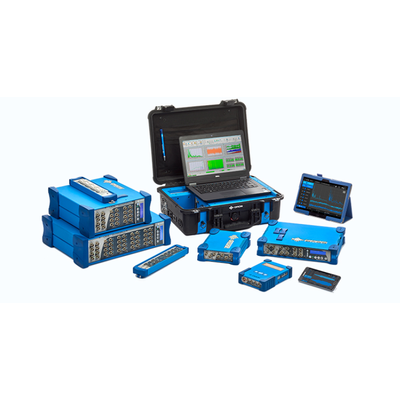
OROS Balancing Solutions are software modules for balancing rigid and flexible rotors. These modules are well–suited for shop balancing or in–situ field balancing. They are designed to run on OROS analyzers.
2 modules are available:
Single/Dual plane software module
It is particularly suited for shop or field balancing of rotors operating in their rigid body region (well below their first critical speed).
Multiplane software module
It is designed to balance rotors above the first critical speed: meaning in the region where the rotor deforms and reaches its first bending mode.
Flexible acquisition
- Acquisition from a wide choice of hardware platforms (sizes and weights) thanks to the OROS 3–Series instruments’ range’s flexibility.
- Accepts signals from accelerometers, velocimeters or proximity probes.
- Up to 32 sensors depending on the instrument platform.
Accurate balancing
- Source data for the balancing operation (1X amplitude and phase) provided in real time by the powerful OROS Synchronous
Order Analysis plug–in analysis engine reputed for its high precision.
- Oversampled tach input at 6.4 MHz to provide the best phase accuracy.
- High quality digital signal provided by the state of the art electronics of the OROS instruments.
Designed for efficiency
- Correction planes and measurement planes managed independently and flexibly,
- Flexible weight map configuration with correction mass split or by step of 1°,
- Add or remove weight by drilling,
- Keep or remove test mass,
- Prognostics of residual vibration (“what if” feature),
- Trim balancing,
- Report generation,
- Available in English, German, and French languages.
- 1 or 2 balancing planes
- Rigid rotors
- 1 to 4 sensors (1 or 2 per bearing)
- Real time acquisition and 1X polar diagram (amplitude and phase).
- Steady state speed acquisition
- Acceptance of residual unbalance according to ISO 1940 / Balancing quality selection
- Size and weight: optimum size with O4. Runs on the OROS instruments’ platform
- Trim Balancing
- Report generation
- Designed for non–experts
Being guided by the wizard, the user can perform a balancing operation in a few clicks and without any special knowledge about balancing theory: Training time is reduced.
It is designed for shop or field balancing. Steps to the balancing report are optimized and guided. Testing and correction time are minimized. Thanks to the dedicated interface, the risk for errors is limited.
Practical and applied tools for user ease and efficiency
Based on the acceptance circle the residual unbalance is compared to the acceptable level required by ISO 1940(based on rotorweight, balancing quality grade and operating speed should be provided).
Using the unique prognostics feature, and providing the actual correction mass implemented, the residual unbalance can be easily estimated and compared to the acceptable level.
The history of one rotor can be saved in the project and trim balancing allows further balancing with no
requirement for carrying additional trial tests.
The report feature lets the user print a balancing report and keep track of the modifications made.
Multiplane Balancing (ORNVS-BAL-MP)
- 1 to 14 planes
- Flexible or rigid rotors
- Up to 32 channels for 1X acquisition
- Import 1X data (Amplitude and Phase vs. RPM from ORBIGate or from manual input from text files (csv template)).
- Run–up, Coast–down, steady–state
- Balance at multiple speeds or ranges of speeds
- Calculate predicted Amplitude vs. RPM after balancing correction
- Multiplane report generation
Multiplane balancing is a delicate operation that requires a high level of expertise from the user. The rotor is operated above its first critical speed and will be deformed. The purpose of OROS’ multiplane balancing module is to bring a simple and dedicated tool to the fingertips of the user to solve this complex problem.
Based on the OROS multichannel instruments the 1X data are collected real–time during transients (run–up, coast–down) or steady–state phase at the different steps of the balancing operation (initial, trial, trim). At that stage, the data are displayed as Bode or Polar diagrams. Data can also be entered via other collecting sources including manual input.
The data are then processed offline in the software after selection of the speeds for which unbalance should be reduced.
The residual unbalance after implementation of the correction masses can be calculated for the different speeds of the transient.