

- Home
- Companies
- PSE Petroleum Engineering Software, by ...
- Software
- PSE - Petroleum Structural Engineering ...

PSE - Petroleum Structural Engineering Software
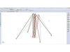
The PSE Petroleum Structural Engineering software is an integrated analysis and design software for Offshore and Onshore structural engineering.
This engineering software solution is used worldwide by several notable international companies in production work for building innovative structures in the Oil&Gas. The PSE software is an advanced structural program based on more than 37 years of Research and Development.
The Petroleum Structural Engineering software is a technology built on a powerful user-friendly interface offering comprehensive analysis options and intuitive modeling features. The advanced structural analysis of the PSE software allows the user to achieve specialized analyses crucial to any projects related to the Oil&Gas industry.
Perform Advanced Structural Analysis
The Petroleum Structural Engineering® software is a technology built on a powerful user-friendly interface offering comprehensive analysis options and intuitive modeling features.
The advanced structural analysis of the PSE software allows the engineer to achieve specialized analyses crucial to offshore and onshore projects related to the oil and gas industry.
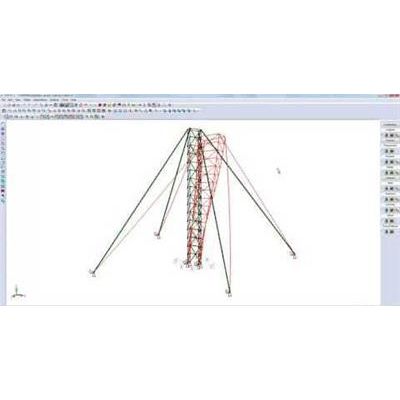
The PSE Petroleum Structural Engineering® software accounts for advanced structural analysis, FEA, wind loads, vessel dynamic motions as well as wave and current loads. Other loads such as seismic, snow and ice loads for far northern extreme weather are also considered for the design of masts, derricks, platforms and substructures.
The PSE software has comprehensive structural analysis methods such as: FEA Finite Elements Analysis, Static Analysis, Linear and Nonlinear Analysis, P-Delta Analysis, Natural Frequency Analysis, Static Equivalent Seismic Analysis, Dynamic Time-History Analysis, Seismic Time-History Analysis, Modal Analysis, Spatial Objects and Spatial Loads, Buckling Analysis, Response Spectrum Analysis, Advanced Section Stress Analysis, Torsion and Warping, Built Up Sections, Catenary Cables, Nonlinear springs, Diaphragm Analysis, Horizontal Notional Loads, Loads and Load Combinations.
State-of-the-art analysis tools
FEA including plates and shell elements Torsion including restrained warping of open sections Linear and exact non-linear cable elements (catenary cables)
Non-linear analysis using load control and displacement control strategy for better convergence Possibility to add non-structural components using spatial objects
Complying with seismic requirements
Automated static equivalent method of the building codes (NBCC and IBC) Seismic response spectrum, seismic time-history, and dynamic time-history analysis Customized response spectrums and accelerograms Fully customizable analysis parameters Maximal response using CQC and SRSS methods Automated or user defined damping Graphical display of response spectrums and accelerograms User defined incidence angle of seismic loads and vertical components Customized analysis and output time steps Time-history results can be provided for selected parts of the models
Benefit from result animation
The PSE software allows users to animate results from different types of analysis such as:
Static linear analysis
Static P-Delta analysis
Buckling analysis
Natural frequencies analysis
Seismic and dynamic analysis
Users can animate various static linear and P-Delta analysis results such as:
Structure displacements
Internal forces
Stresses
Support reactions
Frequency and Buckling
The frequency and buckling analysis provide multiple mode shapes describing multiple behaviors of the structure. With large models, the animation is helpful to discern and understand the mode shapes. It is easier to determine if the buckling mode is a local or global phenomenon. It also provides a very accurate interpretation of the participating mass of each mode in a seismic spectral analysis.
Time-History
The animation function displays every saved time-step to provide an accurate representation of the displacements, velocities, accelerations and internal forces acting on the structure. This will provide users a better understanding of the structure behavior during the dynamic event, such as finding the critical time of the dynamic loading. Animating the envelopes helps minimizing the amount of information on the screen. Users can focus on the most critical regions of the model.
The PSE software considers restrained warping for the torsion of thin-wall open sections. Notice that this phenomenon is not included in most commonly used frame analysis programs. Almost all frame programs in practice use St-Venant torsion theory ignoring the effects of restrained warping.
Spatial objects are used to model non-structural secondary elements attached to the structure. These elements add no stiffness to the existing model.
Loads applied to spatial objects are transferred to the structure through one or more attach joints. The loads are transferred using a “rigid plate” approach. Concentrated, pressure and wind loads may be applied to spatial objects. The figures below shows a spatial object loaded vertically and horizontally attached to a cantilever column.
Also, it shows the deformations and biaxial moments induced by the loads transferred by the spatial object.
Direct Analysis Method (DAM) available for AISC 360-16 and AISC 360-10 standards. The options for the Stability Design Method are Direct Analysis Method (DAM) and Effective Length Method (kL).
The catenary cable element is a highly non-linear element used to model the catenary behavior of a cable suspended between two points under the effect of its self-weight. This formulation accounts for the non-linearity due to large displacements.
A cable has no bending, shear, compression or torsion stiffness. Due to this fact, the fixities at the ends are ignored; the cable is always treated as member acting in tension only. In the interface of the PSE, the user can create a catenary cable by associating a cable type section to a member.