

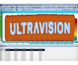
UltraVision - Version 3 -Complete UT and Phased Array Inspection Software
Zetec’s UltraVision 3 software manages ultrasonic (UT) signal acquisition, displays real-time imaging of these signals and provides online as well as offline data analysis. UltraVision offers many advanced features and tools that improve the efficiency of UT inspections. The UltraVision 3 software drives all Zetec’s in-house phased array UT and conventional UT systems. In data analysis mode it supports legacy file formats (DAT, RDT, OPD and OUD) in addition to the new UVData and BeamData formats. The look-and-feel of UltraVision 3 will be very familiar for the seasoned UltraVision 1 user.
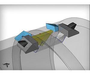
The integrated 3D work environment allows you to create your actual inspection configuration in UltraVision 3 and perform ray tracing with coverage mapping to determine your detection capability and inspection coverage.
Inspection parameters and results are delivered in a comprehensive report. The ultrasonic inspection software is intuitive and allows users to easily design and simulate an inspection.
UltraVision supports many advanced ultrasonic inspection techniques & methods
UltraVision provides value and support along critical inspection processes when reliability, performance and ease of use are required.
Operates efficiently on powerful laptops as well as high-end desktops, under various Windows operating systems.
Technique development
The development of the inspection technique is the start of every ultrasonic inspection. Basic inspection techniques can be drafted manually or on third party software but this is time consuming and requires transfer. UltraVision provides an extended set of capabilities for complex and custom geometries.
- Basic to Complex Geometries Management
- Custom Geometries Handling
- Scanner Creation Tool
- Overlays
UltraVision features an advanced focal law calculator. One that is one common for the entire Zetec UT portfolio. This can handle probes with up to 256 elements and takes into consideration the embedded probe, the wedge and the material database. Graphical feedback is provided on focal law generation. Focal law calculation supporting Flat and cylindrical geometries is easy fast and accurate to ensure that probes are positioned optimally for the inspection. The focal law calculator supports all advanced ultrasonic inspection techniques, including Phased Array Pulse Echo, Pitch and Catch, Tandem mono and dual, plus conventional TOFD. UltraVision supports flexible probes, which have the ability to adapt themselves to irregular inspected surfaces. UltraVision can calculate focal laws to match the surface profile.
UltraVision will design a probe to meet the application requirements, assessing the theoretical parameters, calculating beam parameters and providing a 3D simulation of the acoustic beam. It will also simulate beam behavior if any of the channels are defective. Additionally, calculated wedge parameters can be exported to facilitate wedge manufacture.
- In Setup Building, UltraVision can effectively take care of user rights management (from individuals to groups) ensuring the integrity of the inspection. UT Parameter, Mechanical and screen view settings can all be restricted to defined users or groups
- For Calibration, various tools are available to check the calibration of mechanical and UT parameters. Plus automatic probe detection identifies connected probes, reads probe parameters, serial number and tracks any probe changes
- Regarding Data Acquisition, UltraVision acquires all the relevant data necessary for accurate and reliable inspections. This data is stored in a data file that can reach up to 20GB and can be filed or exported, according to user requirements
UltraVision’s powerful data analysis features provide an inspection advantage.
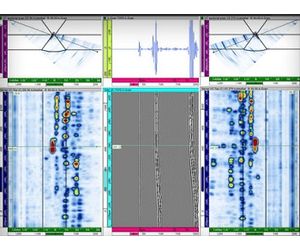
- Views and Axis: Provides a range of advanced views, which can be uncorrected, corrected linked or in 3 Dimensions. The software can also convert between Cartesian and Polar coordinate systems and can convert the Linear to Logarithmic signals
- Analysis Support: A large set of tools is available to assist with data analysis and sizing indications
- File Management: Data can be filed or exported according to user requirements
- Processing Tools: UltraVision also features a range of processing tools offering various data display formats and corrective processing. The original raw data is never compromised
- Parameters: All UT and mechanical parameters can be reviewed and displayed in information fields. Customized information is filed with dynamic links to Excel where specific calculations can be performed
With UltraVision, reporting is highly flexible and powerful. Indications are automatically published in an exportable indications’ table. It can be exported in Excel or as a complete report. Additional configurable user fields can be created to provide added information in the report. Indications are directly plotted on a 3D view of the inspected specimen. Best of all, a wide range of predefined reports are available to facilitate the reporting process.
UltraVision is packed with powerful features that improve inspection analysis and reporting.
Specimen Settings
- Basic to complex geometries managements: UltraVision contains a comprehensive bank of configurable predefined specimens including connecting pipes, cruciform joints, T and L joints.
- Custom Geometries Handling: UltraVision features a number of ways to create specimen geometry. It has a tool to create specimen geometrymanually and an onboard specimen geometrygenerator, which uses the profile scanned from a mechanical profile gage. 3D Custom specimens can also be produced from .SAT files. Finally, it is possible to import a file from ESBeamTool.
- Overlays: Configurable welds can be added to specimens such as V, mod V, X, J, K. Weld profiles can be imported from ESBeamTool.
SETUP CREATION
- Scanner Creation Tool: The scanner creation tool allows a user to simulate the probe position and related UT data on 3D component.
- Beam Simulation:
- Advanced PA Calculator: The focal law calculator supports all advanced ultrasonic inspection techniques, including Phased Array Pulse Echo, Pitch and Catch, Tandem mono and dual and conventional TOFD.
- Automatic Probe Detection: Automatic probe detection detects and identifies connected probes, reads probe parameters and serial number and tracks any probe changes.
- Calibration Tools: Calibration tools calibrate the encoder, the time of flight and velocity for TOFD probes, PA wedge delay, sensitivity and TCG. Individual elements are checked in PA arrays. The calibration block is defined and a calibration check report generated.
VIEWS
- View layout: User rights also extend to deciding how data is displayed on the screen. Users can select sectorial, scrolling, Volume corrected (B, C and D), Polar, A-Scan, FFT, 3D, Amplitude or Time of flight C-scans.
- Customization: Predefined custom layout management can also be selected to view customized properties, such as envelop, smoothing units, overlays and links between views where the cursor movement can be linked. There is no limitation to the number of channels viewed.
- Color Palette Editor: A color palette allows amplitude and TOFD data to be displayed according to user preference.
- UT data acquisition can be 8, 12 or 16 bits and the data file size can be up to 20GB.
- A-scan length can be up to 256000 points per A-scan and every elementary a-scan is captured.
- UltraVision is capable to create and display merged views in real time.
- Mechanical setting allows single point (free running), one line scans, and bi-directional, uni-directional, helicoidally and polar sequences.
- Motorized acquisition: The probe’s positions are controlled from the ZMC2, ZMC4 or MCDU motion controllers. It is possible to collect position information from up to 6 encoders and focal laws can be adapted depending on the probe position. The start, stop and pause of data acquisition are directly controlled from UltraVision 3.
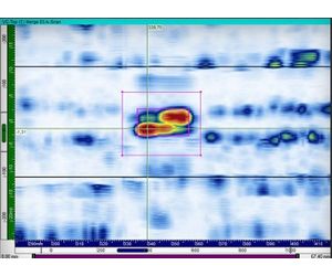
- Sizing Tools: Slicing cursors allow easy measurement while the ability to draw contours around indications assists manual sizing. An automatic Dropsizing tool of allows sizing of the indication within the drawn contour using the dB drop method. Echo dynamic sizing is also available.
- Assisted Analysis: Analysis can also be carried out by automatically screening the entire data file and indicating the areas of interest based on specific, user-selected criteria.
- 3D Data Plotting: By synchronizing A-scans and 2D and 3D data, the software can plot indications and create 3D images.
- Volumetric Processing: Volumetric processing involves merging, volumetric merging and smoothing to produce a software C-scan. A 2D specimen overlay in Top, Side and End views can also be applied.
- TOFD Processing: Tools are available for hysteresis correction, geometric echo removal and TOFD Processing (LW Synchronization, LW Removal, SAFT).
- Indication Table: The indications’ table is automatically populated by selected information fields and can be exported to a text file.
- User information fields: Configurable user fields can be created to provide additional information in the report.
- 3D views in Reports: Indications are directly plotted on the 3D view of the inspected specimen.