

- Home
- Companies
- Inventec B.V.
- Products
Inventec B.V. products
Civil/Structural

Structural Health Monitoring Sensors (SHM)
Structural Health Monitoring enables the owner to monitor the structural integrity of his asset (e.g. bridge, tunnel, building, pipeline or even a dike) over its entire life span and to put it, when so desired, under `intensive care` from time to time. To this end permanent sensors are embedded in or mounted on critical parts of the structure. Whenever deformations and stresses reach specific pre-set magnitudes, the SHM-system automatically raises a warning or an alarm. Thus the owner or asset manager is in a position to take relevant action in time. Even recent history has shown that a structural monitoring system for certain assets is a real necessity.
Wireless Structural Health Monitoring
A typical Inventec wireless structural monitoring package is composed of a number of battery powered sensor nodes that are attached to the structure and that communicate in wireless mode with a gateway node. One single gateway is capable of accommodating up to 1000 sensors. The gateway node transmits the measurement data wirelessly to a server that runs the SenScope software. The measurement data are visualised and archived in Livesense®, Inventec’s web platform for structural monitoring applications. By logging-in on Livesense® our clients can follow the structural behaviour of their asset in real-time and assess its condition by evaluating the measurements over extended periods of time. The parameters that can be measured are vibration, strain, inclination, displacement, temperature and humidity. Once the system is in place the individual sensor nodes can be managed and (re)programmed wirelessly if so desired.
Geotechnical
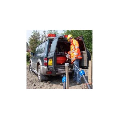
Soil Settlement Measuring System
The system basically consists of a measurement probe containing a pressure transmitter that, via a hose on a reel, is connected to a liquid reservoir. The probe is pulled through the settlement pipe or drain line with intervals, (e.g. 1,00m, 2,00m, 5,00m etc). Recording the hydrostatic pressure at each interval results in the relative profile of the pipe`s level. By subsequently putting the probe on a fixed point outside the pipe it is possible to relate the pipe`s profile to the national grid level. By repeating the measurement with time intervals the progression of the settlement of the subsoil is determined in a very accurate manner. To ensure maximum accuracy each measurement is automatically compensated for variations in temperature and atmospheric pressure. The measurement vehicle is fitted with an automatic processor/datalogger so that the readings can be made available right on the spot, if so required.
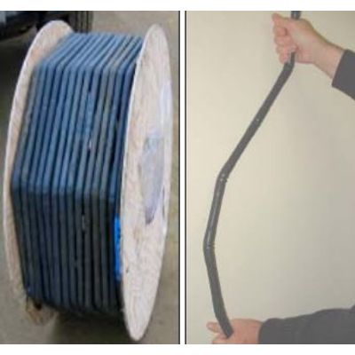
Articulated Chain Of Sensor
The ShapeAccelArray/Field (SAAF) consists of an articulated chain of sensor elements (segments) each 0,305m or 0,500m long. The segments are joined together in such a manner that they can move in relation to each other in all directions except for twisting. Each segment contains a multi-axial MEMS- chip accelerometer. This makes the segment act as an extremely accurate inclinometer that determines the angle of inclination in both X- and Y-direction. Due to its articulated construction the SAAF is capable of following the deformation of the soil very precisely. The diameter of the SAAF is only 25mm. Therefore it can be installed in a flexible PVC-pipe with an outside diameter of only 32mm.
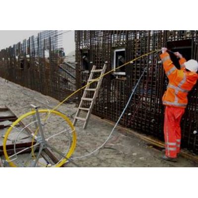
Anchorview
THE SHAPE OF GROUT ANCHORS: On construction drawings grout injection anchors are drawn as straight lines. Practice can be quite different: during the drilling process anchors can easily deviate from the intended path, both in horizontal and vertical direction, due to a number of causes. Having a shape that differs from the design can seriously affect the retaining strength of a grout anchor. And there can be additional reasons why one would want to know the real three-dimensional shape of the anchor after it has been put into place. This is now possible with ANCHORVIEW using the SAAF
Piping
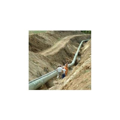
Pipealert - Fiber Optic System
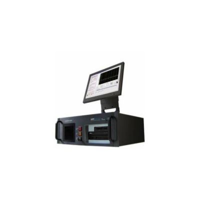
PIPEALERT is a fiber optic system to monitor the structural behaviour of long distance Pipelines and to act as an early warning system for possible leakages. A light pulse of a specific wavelength is constantly launched into the fibers that are connected to or running along the pipe. A reading unit analyses the backscattered light with a spacial resolution of 1,00m, resulting in the truly distributed picture of events along the full length of the pipeline.
Leak Detection and Distributed Temperature Measurement Sensing System
A reading unit constantly launches a high frequency light pulse of one specific wave length through an optical fiber. The major part of the light exits the fiber at the far end. A small part of the light however is backscattered to the reading unit. This backscattering occurs at every point along the fiber. As a result of photo-acoustic phenomena the backscattered spectrum does not only show the original frequency of the light that is launched into the fiber but contains two additional frequencies: the so-called Brillouin and Raman frequencies. The latter is utilised in DTS: there is a defined relation between the intensity of the Raman frequency and the temperature of the fiber. Measuring the Raman frequency at length intervals of e.g. 1,00m results in the distributed temperature over the length of the fiber and thus of the object (e.g. a pipe line) to which the fiber is connected or of the medium (e.g. soil) in which the fiber is embedded.
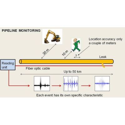
Distributed Acoustic Sensing
The system consists of an optical fiber that is connected to a reading unit. The fiber cable generally will be underground. The reading unit constantly launches a high frequency light pulse through the fiber and analyses the backscattered spectrum. Any activity (such as a walking person or moving car) up to a certain distance from the fiber or even a pipe leak produces acoustic energy that is absorbed by the molecules of the fiber material. This causes a phase shift in the backscattered spectrum that is analysed by the reading unit. The location of an event results from measuring the time that has lapsed between launching of the pulse and receipt of the backscattered light (Radar principle – the speed of light is constant). One single reading unit can detect an event with a couple of meters accuracy over distances up to 50km.