
4B - Model IE-GuardFlex -IE-GuardFlex

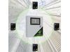
The IE-GuardFlex serves as the central control unit for 4B’s Distributed Hazard Monitoring Solution (DHMS). Utilizing industrial Ethernet technology, the IE-GuardFlex controller connects to and monitors various machine-mounted sensors through 4B's advanced IE-Nodes. This comprehensive system can be configured to support multiple machines, IE-Nodes, and sensors, interfacing directly with the machine's MCCs to perform a controlled shutdown if a hazardous condition is detected.
Typically installed within the plant's MCC and dust hazard "safe area," the IE-GuardFlex system connects via industrial Ethernet (CAT6 cabling) to IE-Nodes distributed near the monitored machines in the "hazardous area." These machines commonly include bucket elevators, enclosed conveyors, open conveyors, chain conveyors, and roll stands. A variety of 4B hazard monitoring sensors are linked to the local IE-Nodes, detecting hazardous conditions such as belt slip (SlipSwitch, Milli-Speed), belt misalignment (TouchSwitch, Bulldog), bearing temperature (ADB, Milli-Temp), vibration (Milli-Vib), and blocked chute (Binswitch).
Once all IE-Nodes and sensors are connected, the plant engineer can initiate the node search process using an intuitive GUI on the 7” color touchscreen display. Detected nodes can be configured, and sensors can be allocated to user-defined machines. The system supports a three-stage ALARM / STOP configuration for each sensor. Output relays can be assigned to ALARM and/or STOP conditions either per sensor or per machine. Additionally, common ALARM and STOP output relays indicate whether an alarm or stop condition is present on any connected sensors.