

- Home
- Companies
- NSI-MI Technologies
- Products
- Commercial Radome Test Systems
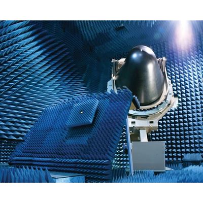
Commercial Radome Test Systems
NSI-MI Technologies’ Commercial Radome Systems are intended for after-repair testing of commercial aircraft radomes. The systems are capable of making measurements described in the widely referenced document DO-213A. After repair, radome testing includes transmission efficiency Sidelobe Level (SLL) measurements. Test systems are available in both C band (5.3 GHz to 5.74 GHz) and X band (9.3 GHz to 9.5 GHz) frequency ranges.
- Highly accurate and repeatable results
- Easy to use and maintain
- Scalable system allows for future expansion
- System software generates automatic test results
- Test system supports all current radome sizes
- Most affordable system on the market today
- Guaranteed test results that meet or exceed RTCA/DO-213A
NSI-MI Technologies offers a complete line of products for testing commercial and military radomes. Our solutions can be configured to provide an RTCA/DO-213A compliant electromagnetic test facility to test for the requirements contained in Section 2.2 of the standard. A turn-key test system or individual product solution can be provided to help the user develop a test plan.
A radome’s performance is dependent on its ability to provide physical protection to the weather radar antenna and its electrical ability to provide two-way transmission of radar signals with minimum distortion and absorption. Radar efficiency, resolution, and accuracy of display depend upon a clear, non-distorted reflection-free antenna view through the radome. A radome’s construction and electrical performance are such that even the slightest change in physical characteristics, such as excessive layers of paint, can adversely affect the weather radar and windshear detection system performance. An improperly manufactured or repaired radome can result in:
- Reduced radar range or signal loss
- Distortion and displacement of target weather phenomena (i.e. a line of thunderstorms directly ahead may appear to be off to the left or right)
- Clutter on the display obscuring the target
- Improper windshear avoidance performance
- No moving cables
- Highly repeatable rotary joints in the two antenna axes (no other moving RF parts)
- Antenna alignment does not depend on radome positioner accuracy or dynamics
- System antenna and range are precisely and permanently aligned
- Built-in compensation for drift in source, cables, and amplifier
Positioning Sub-System
- Radome Positioner
- Test Antenna Positioner
- Source Antenna Positioner
- Position Control Electronics and Software
RF Measurement System Sub-System
- RF Measurement Instrumentation
- Cables, Adapters, Amplifiers to form a complete system
- Data Acquisition and Analysis Workstation