
Microwave sensor for on-line mass flow measurement of solids up to 20 t/h. Used in pneumatic leanphase conveying or vertical freefall after mechanical feeders.
- easy installation via weld-on socket
- for almost all types of dusts, powders, granules
- uses field-proven technology with active roping compensation
- suitable for nearly all pipe diameters
- Simple retrofitting using a welding socket
- ATEX-certified
- Almost all types of dust, powder and granules can be measured
- No installations in the material stream
- Measuring principle: Microwave
- Online flow metering
- Throughput measuring flowrates up to 20 t/h
- Active roping compensation for highest reliability
- Wear-resistant
- Biomass
- Cement
- Chemistry
- Coal plant
- Coating
- Food
- Incineration
- Minerals
- Wood
- Lime plant
- Energy
- Gypsum
- Power plant
- Foundry
- Material to measure: Dust, powders or granulates max. grain size 20 mm
- Working principle: Microwave
- Process pressure: 1 bar, optional 10 bar
- Process temperature: +200°C, optional up to +900°C
- Mounting: Via process connection
- Type of Conveying: Pneumatic leanphase, vertical freefall after feeder
- Flow rates: Up to 20 t/h
- Pipe diameter: Max. 800mm
- ATEX rating: Category 1/2
- Output: 4…20mA, Modbus, Profibus
Using:
SolidFlow 2.0 is a sensor especially developed for measuring the flow rate of solids conveyed in metallic ducts.
It has successfully been tested for online-measuring of:
- all types of dust, powder and granulates
- grain size between 1 nm and 1 cm
- pneumatically conveyed materials or
- in free fall after mechanical conveying systems
- SolidFlow is wear-resistant and the commissioning is very easy.
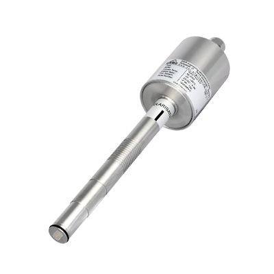
- Housing: Stainless steel 1.4571
- Protection category: IP 65, DustEx zone 20 or
- GasEx zone 1 (optional)
- Operating temperature: Front end of sensor: -20… +80 °C
- Optional: -20 … +200 °C
- Sensor electronic: 0 … +60 °C
- Max. working pressure: 1 bar, optional 10 bar
- Working frequency: K-Band 24.125 GHz, ±100 MHz
- Transmitting power: Max. 5 mW
- Weight: 1.3 kg
- Dimensions: Ø 60, Ø 20, L 271 mm
- Accuracy: ± 2 … 5 % in calibrated range
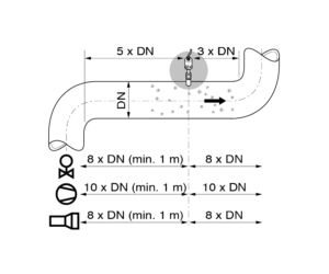
For the assembly of the sensor, the installation location is specified in accordance with the conveyed inlet and outlet paths.
In case of pipe diameters over 200 mm, 2 or 3 sensors per measuring point are used, with the sensors arranged at 90° or 120° to each other.
In free-fall applications (e. g. after conveyor screws or rotary conveyors), an inlet path (fall height) of at least 300 mm is ideal. Shorter inlet paths are possible by agreement.
The sensor bracket (welding socket) is welded on at the specified installation location.
After this, a 20 mm-borehole is drilled through the sensor bracket and through the pipe wall. The sensor is then adjusted to the wall thickness, inserted and fixed with the help of the coupling nut. Done!
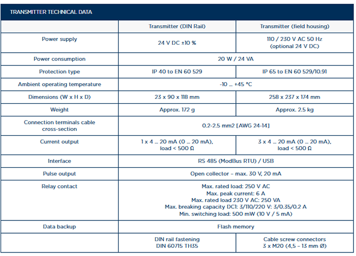
Commissioning:
The commissioning of the measuring device takes place via the FME analysis electronics. These electronics offer a convenient, menu-driven input of parameters such as measuring range, desired physical units or measuring signal attenuation.
The available outputs are a current output, 4…20 mA as well as a pulse output (open collector).
The menu language options are German, English or French.