
ENVEA - Model PicoFlow -Flow Measurement Instruments for Low Solid/Air Ratios
Perfectly adapted for control and regulation of reagent in flue gas treatment and transport lines with very low material concentration.
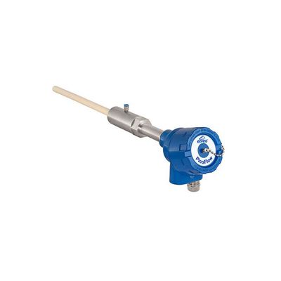
Electrodynamic flow sensor for measurement of low flow rates. For pipe diameters up to 1 m. Ideally used in leanphase conveying. In free fall conditions with at least 2 m/s drop speed.
- Suitable for very low concentrations
- Ceramic coating preventing sensor wear
- Particularly good in pneumatic applications for material flow rates from a few g/h up to a few hundreds kg/h (depending on application)
- Very reliable for free-fall applications with a drop speed of at least 2 m/s (approx. 25 cm drop height)
- In cases where dust measuring instruments cannot cope and flow rate measuring instruments are overspecified
- The Picoflow is perfectly suited for industrial applications especially in power generation or cement plants where it can be used to regulate or control additional reagent in flue gas treatment: injection of activated carbon, minsorb, lignite coke…
- Waste incineration
- Steel
- Chemistry
- Energy
- Cement
- Pharma
- Material to measure: Dust, powders or granulates max. grain size 10 mm
- Working principle: Electrodynamic
- Process pressure: max. 10 bar
- Process temperature: +150°C
- Mounting: Via process connection
- Type of Conveying: Pneumatic leanphase, vertical freefall after feeder
- Flow rates: Depending on application
- Pipe diameter: Max. 1000 mm
- ATEX rating: Category 1/2
- Output: 4…20mA, Modbus, Profibus
- Pneumatic conveying and free fall
- Absolute measurements in g/h or kg/h
- Materials: all types of dust, powder and granules
- Wear-resistent
Sensor Technical Data
- Housing: Stainless steel 1.4571
- Protection Type: IP 66; ATEX: Cat. 1/2 GD
- Operation temperature: Process: -20 … +150 °C
- Ambient: -20 … + 60 °C
- Max. working pressure: 10 bar
- Weight: 1,5 kg
- Sensor rod: Stainless steel, ceramic coated,
- max. 450 mm
- Accuracy: ± 5 % in calibrated range
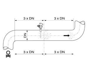
The PicoFlow can be installed in metallic ducts and pipelines.
It should be installed as far as possible away from curves and other fittings such as valves and slides. The distance between the sensor rod and fittings in the duct should be at least three times the duct diameter in every flow direction.
Non-metallic ducts must be cased with a metal sleeve, a metal foil or a tight-mesh metal grille over a length of at least five times the duct diameter.
After deciding the installation location, drill a hole in the duct wall where the supplied weld-on socket can be welded perpendicular to the pipe. Then screw the sensor rod into the socket using the screw-in thread.