
- Home
- Companies
- GW Sprinkler A/S
- Products
- GW - Model C300 - Fire Pump Control ...
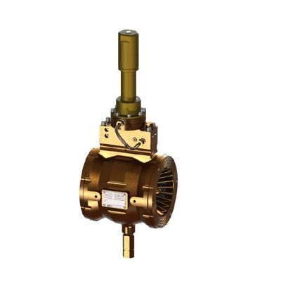
GW - Model C300 -Fire Pump Control Valve
This valve is used where excessive uncontrolled pressure surges from the kick-in of fire pumps shall be avoided. The C-300 Pump Control valve is installed near the fire pump outlet, and is open in the stand-by position. When the fire pump starts, the full flow capacity of the C-300 Pump Control valve is discharged to drain. Immediately at pump start the C-300 valve pilot will monitor the pumped pressure and starts to close untill the pump pressure equals the pilot set-pressure of the C-300 valve, thus providing a controlled fire pump pressure increase to the pipe system - and preventing the damaging effects of surge and water hammer. For optimum pressure surge control the C300 valve should be selected with a flow capacity 1,5 x pump capacity.
The starting of down hole or submerged impeller dry riser fire water pumps can generate high pressures in the pump casing due to the accelerating water interface hitting the in-line check valve.
Reducing these surge pressures prevents over stressing of pipe work, valves, pump casings and bearings.
Pump start up surge pressures can be controlled to acceptable levels by initially directing the flow of water from the pump to drain through the GW C-300 Pump Control Valve. By gradually reducing the flow to drain, the supply is smoothly directed to the fire protection system.
The pump control valve is required to immediately open with minimum flow resistance at pump start-up, and then close under controlled conditions to bring the system pressure gently onto line.
The GW C-300 Pump Control Valve is interactive with the firewater ring main and is directly operated by the water flow/pressure from the fire pump. Upon operation of the fire pump, the pump riser and pump control pipe work fills with water which then enters the Pump Control Valve inlet under pressure. Air from around the flow control sleeve is immediately vented via the vent valve, thus allowing the Pump Control Valve to open fully. This, in turn, initially directs the flow of water from the fire pump to drain/overboard.
As the pump outlet pressure increases, water passes via the internal filter, through restrictors R1 & R2 (see the P & ID) into the sleeve cavity, thus increasing the pressure in the valve casing and causing the vent valve to close. The Pump Control Valve immediately starts to close in order to build up and control the system pressure. The speed of closing being governed by restrictor R1.
The upstream pressure (supplied by the pump) is constantly sensed by the pilot valve. When the pressure increases to the set point, i.e. the required fire main pressure, the pilot valve closes thus stopping any more water entering the sleeve cavity.
Should the fire main pressure increase to a level above the set point, the pilot valve opens to allow water to flow from the sleeve cavity to overboard, the rate of this being governed by restrictor R3. The draining of the sleeve cavity opens the GW C-300 Pump Control Valve, and allows more water from the pump to be directed to drain – thus maintaining the pump supply at set-pressure.
The GW C-300 Pump Control Valve will continue to control the flow/pressure for as long as the fire pump is running.
The Auto Bleed Valve (PN: CV64.540.01) fitted at the bottom of the valve will drain the sleeve cavity in the stand by unpressurized condition, leaving the C-300 valve fully open.
To enable 100% drainage of the sleeve cavity, the C-300 valve should be fitted in the horizontal position, with the Auto Bleed Valve directed pendent downwards. Allow 20 minutes for full drainage of the valve sleeve cavity.
The Auto Bleed Valve automatically closes when hydraulic pressure is applied to the inlet.
The GW C-300 sprinkler valve is “self-powered” – and utilizes the system upstream (inlet) pressure to regulate and maintain the upstream pressure in line with the pre-determined set-pressure ( = max .allowable pump supply pressure)
The valve principle is “elastomeric sleeve type” where the annular valve orifice is adjustable by expansion/contraction of the rubber flow sleeve.
Horizontally - with the Auto Bleed Valve pointing vertical down. Fits between ANSI /ASME B16.5 Class 150 or 300 lbs. flanges.
The GW C-300 deluge valve is developed and designed for maximum reliability when installed and operated in the harshest on-shore and off-shore environments. To prevent any malfunctioning due to components seizing, sticking or corroding, the number of moving mechanical parts has been reduced to an absolute minimum, and the few moving parts present are ALL 100% isolated from the flow media - i.e. no water contact.
The only moving components in contact with the flow media are the elastomeric parts.
A strainer is fitted in the inlet of the valve center block to prevent any debris from entering the hydraulic pilot regulating system.