

- Home
- Companies
- Integrity Municipal Systems (IMS)
- Products
- IMS - Model Series 31-165 - ...
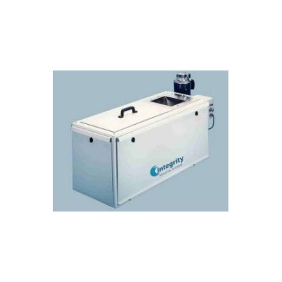
IMS - Model Series 31-165 -Microprocessor Controlled Weighbelt Feeder
The Series 31-165 microprocessor controlled weighbelt feeder controls the feed rate of dry chemicals with an accuracy as low as
0.25% of set rate. Its accuracy and instantaneous response to feed rate changes and variations in material density provide tight control of chemical usages and minimize waste. The controller can provide information about chemical application rate for record keeping or inventory control. The Series 31-165 weighbelt feeder is ideal for industrial and municipal water and wastewater treatment systems or for systems treating industrial process water.
- ƒAccurate and reliable feeder operation
- ƒMicroprocessor controlled gravimetric feeding
- ƒAccuracy better than 1% of rate
- ƒSimple, straight forward man-machine interface
- ƒEasy to install and maintain
- Microprocessor Controlled Gravimetric Feeding to 46200 Ib`hr or 840 ftVhr
Three different sizes inlet sections, 7 gearboxes and 4 driven sprockets provide a wide range of capacity selection and flexibility. Maximum rates cover virtually all water and wastewater chemical feed requirements. - Instant Response, Accuracy Better than 1% of Rate
The precision weigh-scale and microprocessor electronics provide exact control of chemical addition in response to changing process requirements. Costly overfeeding is avoided. - Simple, Straightforward Man-Machine Interface
The setpoint controller has a touch screen for entering commands and parameters. Its menu driven software provides information regarding status, operational parameters, and alarm conditions. Alarm conditions displayed include: low and high feedrate, low and high belt load, low and high belt speed, setpoint and fault condition. - Simple, Automatic Belt Tension and Tracking
Constant and uniform tensioning of the weighbelt is achieved by the use of counterweights acting on the movable front (discharge) roll. A self-adjusting belt tracking device automatically reacts to belt mis-tracking by guiding the belt back to its proper operating position. Both of these mechanisms function together to provide accurate and reliable feeder operation. - Rugged Weighbar Weigh-Scale
The weigh-scale utilizes a sensitive, yet rugged, weighbar to transmit the belt load force directly to a precision load cell. The bar is designed for minimum surface area contact with the weighbelt to reduce belt drag and prevent the belt from sticking to the weigh- scale. It also provides easy access for inspection and cleaning. - Easy to Install and Maintain
All feeders are factory calibrated and tested prior to shipment. A simple field procedure confirms calibration after installation. The need for calculations by the operator and repetitive adjustments are eliminated. The feeder housing is dust-tight. Side and top covers are gasketed and easily removed. The product zone is easily accessible and can be air-cleaned. Sealed bearings are used throughout. Six scrapers spaced on both sides of the belt and on the rollers keep the belt transport free of product build up. The belt transport system is cantilevered for easy belt removal without tools.
Material is supplied to the belt feeder by gravity from an overhead storage bin or hopper. The material is introduced to the belt through the inlet chute. As the belt moves, the material is sheared by a manually adjusted vertical gate which sets the material bed depth. As the material passes over the highly sensitive weigh section, the belt load is transmitted to the precision load cell where a signal is generated proportional to the load. The signal is integrated by the digital controller with the belt speed signal from the motor tachometer to yield a feed rate by weight. The calculated feed rate signal becomes the measured variable in a proprietary PID algorithm, and is compared to the setpoint. If a feed rate deviation exists, belt speed is adjusted by a control signal sent to the DC variable speed drive. Belt speed is automatically increased or decreased until feeder output and set point are matched.
- Feeder Accuracy
Over a 20:1 range with most materials, accuracy is 1 % of set rate or better. Under certain conditions, an accuracy as high as 0.25% of set rate may be achieved. Accuracy percentage is based on the average of ten consecutive samples. The minimum sample size is based on one pound, one minute, or one belt revolution, whichever is greater. After initial calibration and run-in, the feeder will maintain the accuracy stated above for a period of not less than four months without recalibration. - Speed of Response:
Instantaneous response to changes in feed rate and variations in material density. - Feed Rates and Operating Ranges
Maximum volumetric rate: 840 cubic feet per hour
Maximum Gravimetric rate: 46,200 pounds per hour (for a material density of 55 pounds per cubic foot)
Maximum product density: 100 pounds per cubic foot
Maximum operating range: Belt speed of 20:1; Belt load of 3:1
Maximum recommended combined range: 30:1 - Material Characteristics
Particle size: 300 mesh US to VA inch lumps - Inputs/Outputs
Digital Inputs: Remote start/stop from a customer supplied contact closure.
Digital Outputs: Two relays provide unpowered NO & NC contacts for external indication of Feeder Running and Alarm Condition. A third relay provides unpowered NO contacts for Remote Totalization (250 millisecond duration, 2 Hz maximum rate recommended max. rate is 0.5 Hz with mechanical relay). Relay contacts are rated 1 0 amps at 28
VDC or 120 VAC with 80% power factor, or 6.7 amps at 240 VAC with 80% power factor.
Analog Inputs: Remote setpoint input via isolated 4-20 mA or 0-10...2-10 VDC.
Analog Outputs: An isolated 0-20/4-20 mA output signal is proportional to feedrate; maximum allowable loop resistance is 500 ohms. - Serial Interface (optional)
Master/Slave: RS 422
Host computer RS 422 (protocol Siemens 3964R; Allen Bradley DHWY+). - Temperature Limits
Ambient: 14 to 122° F (-10 to 50° C)
Material: 14 to 195° F (-10 to 90° C) standard 0 to 338° F (-18 to 170° C) optional. - Electrical
Power Requirements: 115 volts ±10%, 15 A, single phase, 60 Hz.
Belt Drive Motor: Vi hp, 90 VDC, permanent magnet, TENV, controlled by
SCR drive with tachometer feedback.
Tachometer Analog, 20.8 VDC/1000 rpm, TENV.
Electrical Enclosures: Rated NEMA®4X.
Maximum Distance (Controls to Feeder): 1,000 feet (300 meters).
Display Type: 5.7` High resolution color touch screen - Materials of Construction
Materials in contact with the product flow include a 304ss, nickel plated steel, Buna N, and neoprene. The feeder enclosure is gray epoxy painted mild steel. - Dimensions
See WT.310.165.100 & WT.310.165.102 - Weight and Shipping Weight
260 lbs., 300 lbs.