

- Home
- Companies
- Landini Pompe Srl
- Products
- Landini - Vertical Axis Centrifugal ...
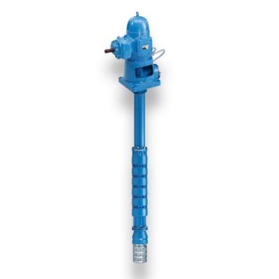
Landini - Vertical Axis Centrifugal Pumps with MG Control
D Series with MG control - Tractor Vertical axis pumps for bored wells D MG Well pumps and electric pumps.
CONTROL UNITS - MG SERIES
The use of a special multiplier equipped with a splined shaft has allowed the coupling of the normal angle transmissions to the power take-offs of standardized tractors at 540 or 1000 rpm, by means of a cardan shaft. As expected on the RA controls, these are also equipped with a water-circulation oil cooling system which in this series also extends to the structure of the multiplier casing, keeping the whole unit at the right operating temperature even in conditions of continuous work and in the presence of very high ambient temperatures.
THE PUMPS
Consisting of a series of modular stages, they are provided with a connection for the upper pipe and normally with a foot valve flanged to a galvanized steel siphon that prevents the entry of foreign bodies into the suction. The pump bodies and the valve body are made of fine-grained gray cast iron, the semi-axial flow impellers dynamically balanced, in cast iron or bronze on request; the pump shaft, guided by wear-resistant rubber bearings, in carbon steel covered with hard chromium or in stainless steel on request.
THE SHAFT LINE
It is made up of an upright pipe made of steel, double-flanged in logs with a standard length of 3 meters. It allows the pump to be positioned in depth and the water to be conveyed. Transmission is ensured by rods guided at each end by wear-resistant rubber bearings which guarantee perfect alignment of the transmission axis throughout the installation depth. At each rubber bearing, the rods are protected by hard chrome-plated brass wear sleeves. The threaded connection sleeves and the rods are made of carbon steel or stainless steel on request. The rubber bearings are placed in the center of a cast iron support interposed between the pipe flanges.
USES
Lifting of deep waters. Installation in bored or open pit wells. Irrigation systems, aqueduct, industrial and fire-fighting applications.
LIMITS OF USE
- Lifting of fresh water mechanically and chemically non-aggressive according to the materials normally used in production.
- Maximum water temperature: 40ºC.
- Maximum water hardness: 40 g / m³.
- Installation depth: up to 120 meters in standard execution.
- Delivery base
- Drive shaft
- Bevel gear
- PTO shaft
- Cooling coil
- Lubrication circuit
- Shaft line
- Pump body
- Impeller
- Pump shaft
- Valve bottom
- Succheruola