
- Home
- Companies
- SkimOil, LLC
- Products
- Model API Oil - Coalescing Oil Water ...
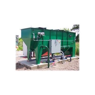
Model API Oil -Coalescing Oil Water Separator
Coalescing oil water separators are passive, physical separation systems designed for removal of oils, fuels, hydraulic fluids, LNAPL and DNAPL products from water. Skimoil’s designed performance can be described by a combination of Stoke’s Law and current coalescing plate theory, wherein, the oil droplet rise rate and other parameters dictate the surface area required for gravity & coalescent separation.
The water/oil mixture enters the separator and is spreadout horizontally, distributed through an energy and turbulence diffusing device. The mixture enters the Flopak media where laminar and sinusoidal flow is established and the oils impinge on the media surface. As oils accumulate they coalesce into larger droplets, rising upward through the pack corrugations until they reach the top of the pack, where they detach and rise to the water’s surface. At the same time solids encounter the media & slide down the corrugations, falling into the v-hopper under the Flopak media.
- Integral oil reservoir
- Forkliftable skid, lifting lugs
- Flat bottom
- Sectional cover w/zinc hardware
- Carbon or Stainless steel construction
- Adjustable water weir
- Expandable effluent chamber
- Epoxy internal/external coatings
- 150 mg/L performa
Gravity separation utilizes the difference in specific gravity between the oil and water. Oil separates from a fluid at a rate explained by Stoke’s Law. The formula predicts how fast an oil droplet will rise or settle through water based on the density and size of the oil droplet size and the distance the object must travel. Our separators are built to exploit both variables of Stokes Law. With the use of our Flopak media oil only need rise a short distance before encountering the oleophilic, coalescing media plates inside the separation chamber as opposed to rising a great distance in gravity separation. Upon impinging on the plates the oils coalesce (gather) into larger droplets until the droplet buoyancy is sufficient to pull away from the media and rise to the water’s surface. The design will meet particular design criteria as indicated below:
- The hydraulic distribution of the influent flow must assure full usage of the cross-sectional area of the media to fully utilize the plate pack’s surface area.
- Flow control and direction must be determined to prevent hydraulic short circuiting around, under or over the media pack.
- A laminar flow condition must be maintained (Reynolds "Re" number less than 500) in order to assist droplets to rise. Per the American Petroleum Institute’s (API) Publication 421 of February 1990.
- Horizontal flow through velocities in the separator must not exceed 3 feet per minute or 15 times the rate of rise of the droplets which ever is smaller.
- The media containment chamber design, plate design/angle and spacing sufficient to facilitate removal of accumulating solids. Plates are to be smooth surfaced and angled at 60 deg.