

- Home
- Companies
- EcoChem Analytics
- Products
- Model MC3 - Multicomponent Analyzer
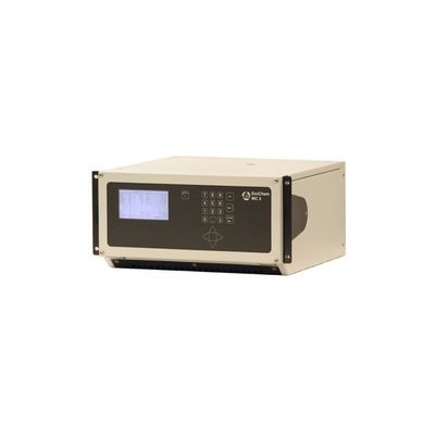
Model MC3 -Multicomponent Analyzer
The MC3 is a multicomponent IR gas analyzer that is specifically designed for continuous monitoring of a flue gas stream. The infrared optical bench, sample cell and control components are all integrated into one convenient, and easily serviced ventilated enclosure.
Optical bench
The infrared optical bench consists primarily of an infrared source with chopper, a sample cell that the infrared light pulses travel through, a motor driven filter disk that can put up to 12 different optical filters or gas filled cells in the infrared light beam, and a solid state detector to measure energy of the infrared light pulses. To understand the operation it is necessary to first understand the underlying analytical techniques.
1a. Gas Filter Correlation Technique
The Gas Filter Correlation technique is a well-known method to reduce cross sensitivities to gases that cause interference in infrared measurements. In the technique an optical band pass filter is used to select an infrared band and then a cell filled with 100% concentration of the gas of interest is placed in the beam, effectively blocking the spectral lines that the gas absorbs at. Alternately with the gas filled cell, a clear aperture with no absorption is placed in the beam. In essence, the gas filled cell is blocking all of the energy in a specific spectral line, creating a reference pulse that is absolutely free of variation due to the gas of interest. The other pulse coming through the clear aperture can be reduced by the gas of interest, thus will vary the ratio of the two pulses with variations of the gas of interest. The result from the IR detector is the presence of two electrical pulses that represent IR energy levels, one missing the energy absorbed by the gas filled cell and the other containing all of the energy of the infrared source. If the IR beam passes through a sample cell that has none of the gas of interest, then the two pulses will be significantly different in amplitude. If the gas of interest is present in the sample cell then the ratio of the two pulses is reduced...in theory if the sample cell concentration is high enough then the two pulses will be the same amplitude with a ratio of 1. The Gas Filter Correlation technique is applicable to any gas that presents adjacent harmonic spectral absorption lines. It is important to note that variations in optical clarity like dirt on cell windows, source strength, and other causes not related to the spectral lines selected, will have no effect on the RATIO of the two pulses, making this an extremely sensitive and selective analytical technique.
1b. Single Beam Dual Wavelength Technique
In the Single Beam Dual Wavelength technique ultra narrow band optical filters are used to select infrared wavelengths. One wavelength is at a spectral line that the gas of interest absorbs (measuring) at, and the other is one at which it does not (reference). Under a zero condition in the sample cell the two cells are alternately placed in the beam and the resultant electrical pulses are set as equal. If the gas of interest is present in the sample cell the measuring pulse is reduced in relation to the reference pulse and the ratio of the two is used to output a signal proportional to concentration in the sample cell. The MC3 analyzer can utilize either of these techniques, depending on the gas to be measured and the range of analysis.
Folded Path Sample Cell
One of the early challenges to be faced by Infrared photometers was that of the sample cell path length. That is the simple problem of trying to place enough molecules into the infrared beam to produce a usable signal. Indeed, many IR applications would have required lengths longer that 60 feet for the lower ranges of analysis, an impossible task for any practical instrument. In the late 60s sample cell developers created a technique that allows very long path lengths to be achieved in compact cells, using mirrors and a folded path technique. Simple and robust they have allowed IR photometers to routinely have paths as long as 20 meters yet remain in small envelopes. The sample cell in the MC3 is fully adjustable for optimization of each application and has reduced volume to save on maintenance and calibration gases. The standard sample cell path is 6 meter however for higher sensitivity it is possible to incorporate a 12 meter path length.
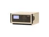
3. Construction
The MC3 is specifically designed for Continuous Emission Monitoring service and the optical bench, sample cell and control components are all integrated into one convenient, and easily serviced enclosure. In particular the integrated design allows the photometer source and detector to be housed in the same temperature controlled housing which significantly improves stability. The filter disk, holding 12 filters each is controlled by a stepper motor. The filters are near 1/2 inch in diameter and the infrared beam is less than 1/8 inch so that alignment of the filters is never critical. The solid state IR detector utilizes the exact same technology as found in the Sidewinder missile. It is located on its own subassembly but in the temperature controlled housing with the IR source and Pre-Amplifier.
4. Inputs and Outputs
The MC3 analyzer communicates with the System PLC using a serial link and Modbus protocol. The System PLC unit can be connected to the plant’s network and standard Ethernet TCP/IP can be used for communications. This is especially useful when a remote data acquisition system is employed. Additional System PLC units can be located anywhere within the plant and the only connection needed to communicate all system analog and digital signals is the plant’s existing network instead of scores of conductors and cable trays. In addition, the analyzer can be controlled via modem, Ethernet or TCP/IP. This feature can greatly simplify complex applications that translate into significant savings of installation cost.
For the measurement of reactive gases such as ammonia or HCl, or in the case of a sample gas with a very high acid dew point temperature it may be necessary to maintain elevated temperatures all the way through the gas analyzer. The HW sampling system can maintain such conditions at temperatures up to 480 ºF. The HW system also includes the unique capability to directly measure stack water vapor content.
The HW5 Probe Assembly provides specific functions needed for reliable sampling of flue gases while closely maintaining temperatures at elevated levels. Those functions are probe-back purge with instrument air, calibration gas injection, and failsafe inerting to protect the system from corrosion if loss of temperature control should occur.
The HW5 Probe Assembly consists of a coarse (20micron) sintered metal filter mounted on the probe tip, a probe tube, and a fine filter body, which is mounted on a 2" 150PSI flange. A probe tube heater for stacks with condensing conditions can be provided. Standard materials of construction include 316L, Hastelloy, Inconel or even titanium.
Filtration is provided in two stages using sintered metal filters. The coarse filter on the probe tip is rated at 20 microns and is protected by an impact shield. External to the flange is the fine filter assembly which houses the second sintered metal filter that is normally selected for 1 micron. Generally this filter does not need servicing but it can be easily accessed without removing the probe from the flange.
Instrument air purging of the probe tip coarse filter is accomplished through the Fine Filter Assembly by use of a one-way valve for injection and operation of a special bellows valve for isolation. How often the probe is back purged is determined by sampling conditions but even with severe particulate conditions no more than four times a day is required.
Like back purging, calibration gas is injected into the probe by a check valve, using the same bellows valve for isolation. The isolation function is of critical importance while calibrating and the HW5 Probe uses a unique air operated bellows valve and seat to provide positive sealing at temperatures as high as 480 F. The back purge, calibration, and isolation valves are all built into the HW5 Probe Assembly and are of course heated and temperature controlled to the same level.
The heat traced sample umbilical will maintain the gases at an appropriate temperature all the way from the Probe Assembly to the analyzer enclosure. Good engineering practice dictates that this be short as possible but it is of more importance to place the analyzer in a convenient location. Lengths up to 500 feet are possible. The sample umbilical bundle will contain one or more tubes for the sample gas and may contain additional tubes for instrument air and calibration gas. It may also have conductors and control wires for other functions needed at the Probe Assembly. The materials of the sample tube may be either Teflon or stainless steel depending on the temperature requirement. Normally the measurement of HCl or ammonia will require the highest sample line temperatures, at about 450 ºF.
The motive force for sample system flow is a special high capacity heated pump. A key in reactive gas sampling is that it is important to minimize residence time in the sampling system and that means the pump must have high capacity. The heated sample pump has been specially designed for this service and has proven to be very reliable.
The analyzer sample cell may be of straight or folded path construction depending on the gases to be measured and range of analysis and may include an integral ZrO2 oxygen sensor. The sample cell is temperature controlled and the sample exhaust is always vented to the atmosphere.
It should be noted that in the Sample System only four parts-- Probe, Sample Line, Pump, and Sample Cell -- are in contact with the flue gas. All parts are highly specialized for this application and in over 400 installations they have performed reliable for extended periods of time.