

- Home
- Companies
- Bladewerx LLC
- Products
- Model microPulser - Programmable Pulse ...
Model microPulser -Programmable Pulse Generator
-
Designed specifically for testing and calibrating radiation monitoring instruments
-
Computer programmable scripts via USB cable with the Assistant PC software
-
Includes all 3 common output connectors: BNC, MHV, Type-C
-
Dual analog and digital displays provide both visual feedback and accurate readings
-
Measures and displays high voltage readings of connected instrument
-
Simple menu-driven setup and calibration
-
Integrated Windows-based software for analysis & control
-
International version available using SI units and adapted power supply
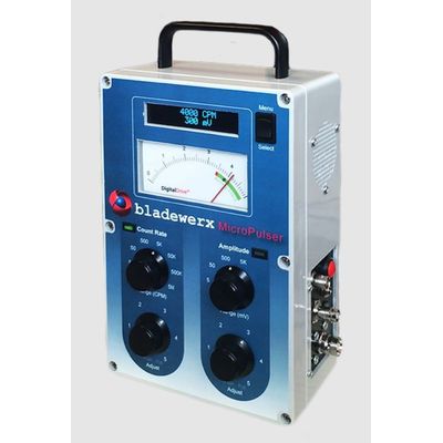
Four controls, on the front face of the microPulser, are grouped in two pairs. The Count Rate pair consists of a rotary switch to select the count rate range, and a linear potentiometer to adjust the rate within the selected range. Through an integrated push/pull switch in the potentiometer, the user can toggle between a ‘snap’ mode—stepping readings by fixed increments—or a continuously-adjustable rate mode. A front panel LED indicates when the analog meter is displaying the count rate while being adjusted.
The other pair of knobs control the pulse Amplitude and operate in a similar manner. The rotary switch selects the amplitude range, and the potentiometer adjusts the amplitude within the selected range. A ‘snap’ and fine amplitude adjustment is available on the Amplitude setting as well. Like the Count Rate LED, an Amplitude LED indicates that the meter is showing the amplitude setting.
A Menu/Select rocker switch in the upper right corner of the microPulser cycles through the simple list of user menu options and selections. A momentary power button on the side of the case turns the unit on or off.
The connected instrument high voltage output is also measured on each of the connectors—choosing the highest voltage found to display. This circuitry is utilized only when measuring the high voltage from the user menu. During normal pulse output mode, the high voltage measurement circuitry is switched off to prevent loading of the signal through the high impedance voltage divider.