

- Home
- Companies
- phil-vision GmbH
- Products
- Model pvCal - Calibration Plates
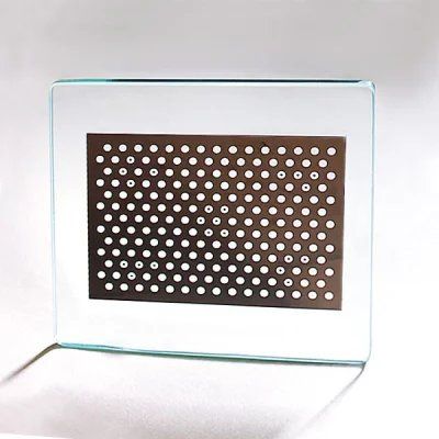
Model pvCal -Calibration Plates
Machine vision and image processing applications often require high accuracy alignment or measurement and calibration of the image produced by the camera in relation to the physical world. This requires a conversion based on a geometric model and the use of a calibration target. The use of calibration plates is also an excellent way to create MSA verifications.
Application areas are extremely diverse:
- You need rectangular pixels in your application and have to "eliminate" the optical distortion caused by the lens and/or a inclined mounting of the camera?
- Your application requires a reference between pixel coordinate system and world coordinate system in order to be able to measure correctly?
- You must record a 3D scene and need to relate several cameras to each other for this purpose?
- You want to set the resolution of your camera system exactly to the focal point?
Obviously, a calibration target is not as important for a vision system as the camera, lens, illumination or vision software, but in order to achieve the highest possible accuracy for your vision application and to obtain precise measurements even in real coordinates, calibration targets are indispensable. Furthermore, since every lens shows distortions, it is necessary to calculate this distortion using a calibration target and thus increase the overall accuracy of the optical system through correct calibration.
A calibration target is a plate, usually made of ceramic or glass, on which a highly accurate pattern is printed. Ceramic is used for frontlight illumination applications, whereas glass plates are used with backlight illumination. Alternatively, carbon or aluminium can also be used as a carrier material.
Which pattern (e.g. dots, checkerboard etc.) is best suited for your application depends largely on the software used and the task. For example, if you want to use Halcon for calibration, you should also use a pattern supported by Halcon.
The size depends on the task and the software used. As a rule, the entire target should be in the camera`s field of view and thus not be larger than the field of view of the camera. However, if the target is too small, you loose accuracy in detecting the pattern in the image.
The required accuracy also depends on the respective application and task. A factor of 10 is a must in any case, but manufacturers of measuring equipment often demand a factor of 20 above the desired accuracy after calibration.
A camera is used to capture images of a special pattern plate (the calibration target) on which positions are marked with high accuracy. Based on these known positions of the patterns and the positions measured in a captured image, the geometric model of the camera is calculated, which can then be used to transform a pixel position in the image into the position in the real scene (e.g. in mm).
-
Correction of the tilt of the sensor to the optical axis
-
The aspect ratio (dx:dy) is not 1:1
-
Perspective distortions caused by a tilted installation of the camera
-
Spherical distortions caused by the optics
-
Barrel distortion, pin cushion distortion, radial distortion, non-linear distortion of autofocus lenses
-
Incorrect alignment of the camera sensor
-
Relation of several cameras to each other e.g. 3D or stitching of images