

- Home
- Companies
- Paul N. Gardner Company (GARDCO)
- Products
- Paul-N-Gardner - Model P.A.T. - Paint ...
Paul-N-Gardner - Model P.A.T. -Paint Adhesion Test Kit
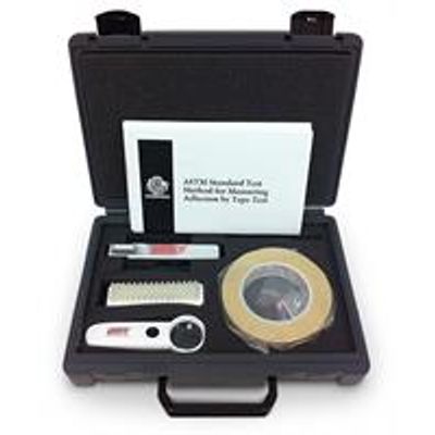
The P-A-T Paint Adhesion Test Kit produced by Gardco contains all of the tools and materials needed, except for the multi-tooth cutter blade, for conducting adhesion tests on paints applied to a flat, uniform surface in accordance with ASTM Test Method D3359, method B and DIN Standard No. 53151. The multi-tooth cutter blade is furnished separately to permit choice among the various available designs.
The kit includes the new blade holder / handle with guide, hex wrench for changing blades, flaking brush, 5x LED hand held magnifier w/batteries (magnifier has 2 LED lights and 1.5" glass lens), tape - PA-280630*, copy of ASTM Test Method D3359 for use as as instruction guide, and a sturdy plastic carrying case with handle. All of the components are nested in laminated diecut foam within the case.
The new ergonomic handle design gives comfortable and precision control. It helps keep your hand in a natural position, preventing strain and fatigue. One handle for both the right or left handed person. Due to the accuracy of the spacings and the speed with which the test can be conducted, the multiple tooth cutter is the preferred tool for use in this test except when evaluations must be made on coatings applied to surfaces which are neither flat or relatively smooth. Under these adverse conditions a single razor blade type cutter is often desirable under method A of ASTM. A Multi-Tooth Adhesion Cutter for pipe is also available.
Multiple tip cutters are available with guide teeth and six spaced teeth at 1.0 and 2.0mm. The 1.0mm spacing is also available with eleven teeth and guide teeth. Available without guide teeth are cutters with eleven spaced teeth at 1.5mm. Also note other cutter blades illustrated in the dimensional drawings. (Ask for information on special variable spaced cutters and cutters for curved surfaces.)
- Prepare test specimen as outlined in ASTM D3359.
- Position the blade in the handle with the holes facing the securing set screws, take care not to over tighten.
- Place the cutter assembly on the test specimen so that the guide and cutter rests on the substrate.
- Grasp handle and rotate it upward with respect to the line of contact of the guide with the test surface. During this motion, the tips of the cutter first contact the test surface when the top of the handle is about seven degrees with respect to the test surface. Continue this motion until the top surface of the handle is elevated to about 15 degrees. This is the correct attitude of the cutter assembly for the test.
- Apply enough pressure on the handle to insure that all of the cutter tips penetrate the test specimen supporting base, pull assembly along the test surface through 0.75 to 1 inch. Repeat this procedure with a second cut intersecting the first pattern at 90° (±5°). Evaluate results of the test as indicated in ASTM D3359, method B.