

- Home
- Companies
- Quilton S.A.
- Products
- Quilton - Hydraulic Waste Compactor
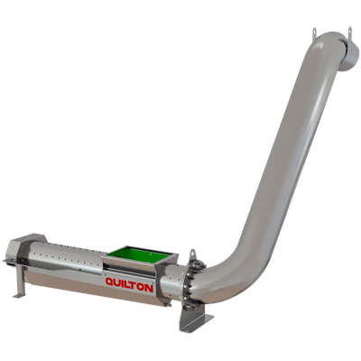
Quilton - Hydraulic Waste Compactor
A QUILTON hydraulic waste compactor is used to transport, compact, and dehydrate wastes and other damp or wet materials obtained from the screening of urban or industrial wastewaters. The wastewaters are discharged into an inlet hopper, where a piston moves, compacts, and dehydrates the wastes. The hydraulic waste compactor’s load capacity varies according to the piston`s diameter and the number of cycles it performs. The waste input volume is reduced by between 40% and 60% after compacting owing are some of the types available:
Proper dehydration by compactingdepends on the following factors:
- Type of raw waters.
- Waste transported.
- Type of mesh or screen and its operating method.
There are three main components in a QUILTON hydraulic compactor: the compacting area, the hydraulic system, and the operating panel and switchboard.
COMPACTING AREA
This basically involves a piston that moves slowly, alternating inside a tubular body mounted beneath a load hopper. The outlet of the tubular body is connected by a flange to the discharge pipe that compacts the wastes and offloads them at a certain distance or height from the compactor. There is a tray under the tubular body for collecting the liquids extracted from the wastes.
HYDRAULIC SYSTEM
This involves a hydraulic cylinder inside the compactor piston powered by the hydraulic drive, at a pressure that may vary between 100 and 200 bars. This pressure is converted into a pushing force ranging between 4,000 and 11,000 kg, depending on the piston diameter.
The hydraulic drive on a QUILTON hydraulic compactor is to be mounted in a dry area that is not susceptible to flooding under normal conditions. It has the following components:
- Filter.
- Oil temperature and level sensor.
- Pump.
- Manometer.
- Safety valve.
- Solenoid.
- Pressure gauge.
- Hydraulic cylinder.
OPERATING PANEL AND SWITCHBOARD
It is used to operate the hydraulic unit, regulate the number of cycles per minute, adjust and control the drive force, etc. If the pressure increases above the set value (caused by a body that is harder than the other wastes, such as a piece of wood) the piston withdraws and the cycle begins again, which avoids any blockage between the piston and the tubular body.
As with the hydraulic drive, it should be located in a dry area that is not susceptible to flooding.
- Compact and aseptic.
- Adaptable inlet and discharge position.
- Possibility of adjusting the degree of dryness via the unit’s pressure.
- Models adapted to inlet flows.
- High dryness rates.