
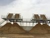
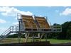
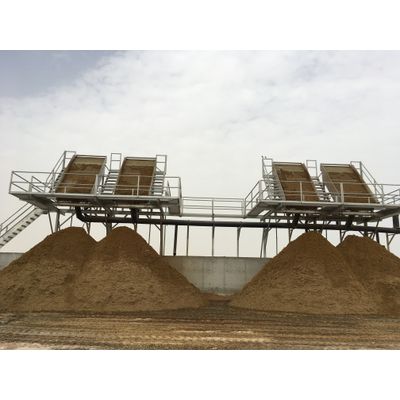
Agpro - Model Mark IV -Screen Separator
Agpro’s® Mark IV line of static screen separator units is designed to separate properly diluted and agitated liquid waste slurries delivered by pump. Split screen design affords both flexibility in selection of weir spacing and enhanced clean ability. Stainless steel construction includes body, rear entry chamber and screens. All units are provided with hot dip galvanized support structure, two access stairways and under screen spray nozzles to facilitate clean up.
General Guidelines
The Agpro Mark IV and Mark V manure separators are designed to separate the excess water from manure-water slurries and provide the operator with more manageable components.
Adequately diluted slurries run over a clean, properly installed separator, will result in separated solids with moisture contents down to 90% or less, and the separated water will normally contain no solids larger than the selected screen spacing. The materials should be stored on a properly constructed and drained floor.
All manure slurries are not alike. The make-up of slurries is affected by these factors and probably others.
- Dilution from rainfall.
- Dilution from other water.
- Evaporation from heat and sunshine.
- Changes in feed ration ingredients.
- Method of cleanup.
- Age of slurry.
- Reuse of cleanup water.
- Introduction of ingredients such as detergents, disinfectants, bedding, waste hay, and waste silage.
- Frequency of cleanup and processing.
With this many variables, it is easy to see that the make-up of manure slurry will vary greatly from one farm to another and, in fact, may vary significantly on the same farm from one day to the next or even from one hour to the next. These separators are best suited to slurries with 4% or less solids contents. Because of this the flow to the separator must be controlled. Provide a pump that has provisions for flow rate control.
Assembly
Refer to assembly drawing for aid in parts identification. Note: Do not tighten bolts until assembly is complete. The unit is shipped partially assembled. Remove all crating and protecting material. Use caution when working around the separator screens. The stainless steel screens are virtually indestructible with normal use; however can be easily damaged by blows from hammers or falling tools.
1. Raise the top end of the separator body allowing the rear leg assembly to pivot out. The separator should now stand with minimal support. The rear leg assembly should be vertical.
2. Attach two horizontal leg-to-body supports(1/2”x 55 7/8” flat) to the tabs on the underside of the body and to the rear leg using (2) ½” X 5” hex bolts to legs & ½” x 1 ¾ on body tab, (8) washers and (4) nuts provided.
3. Install stairs on each side. Insert (3) 1½” square X 46” long tubes into 2” square tubes located horizontally along the back of the separator. These tubes should be inserted with the two sets of stairs mount plates positioned on top and approximately parallel to the back of the separator. Position the stair platform in place. Re-secure nuts to clamp stairs to body. Join the eight stair mount plates (four on ladder, four on 1½” tubes) using (8) 1/2” X 1½” hex bolts, (16) washers and (8) hex nuts provided. Position and attach the side and end handrails to plates located on the outside of the stairs using (8) ½” X 3” hex bolts, (16) washers and (8) hex nuts provided. Attach upper end diagonal strap from lower outside end handrail hole (hardware already installed) to hole at top of separator entry chamber using (1) ½” X 1¼” hex bolt, (2) washers and (1) hex nut provided (shipped already in hole). Finally snap outside corner cap into position to connect side and end handrails.
4. Check to see that all components are assembled and positioned properly. Tighten all bolts and nuts. Note: Do not tighten the bolts retaining the screens to the body.
Installation
Normal installation includes the positioning of the separator on a tower or other platform.
If possible, the separator tower should be constructed so that the screen area of the separator can be seen from the manure collection pit. This will allow the operator to adjust a flow control device positioned at the manure pump to effectively match the pump and separator capacities.
The pump supplier must account for all elevation differentials from bottom of pit to weir distribution of separator in calculating head to adequately size delivery pump. Dimensions will vary at each installation.
The platform should be approximately 10 to 12 feet above the floor where the manure solids are to be accumulated and sturdily constructed to support a minimum of 4,000 pounds. The platform floor will require a slot 20″ wide by the width of the separator across the front of the unit for solids to fall through. The platform should be fitted with a good safe access ladder or stair and totally enclose the separator with safety rails.
In areas where very cold weather is anticipated, an insulated building to house the separator may be needed. The concrete floor below the platform should be sloped to drain away from a push wall and to the manure collection sump or the waste retention pond.
Using Cranes, Skytrack, or other similar equipment place the assembled separator on the platform. Use caution during this process to avoid injury or equipment damage.
Position the separator in place with the solids discharge edge of the unit 2″ beyond the edge of the slot. As required, adjust the separator with shims under the support legs so the top distribution weir pipe is perfectly level. Bolt the separator down to the platform floor.
Plumb from the pump to the separator inlet located at the rear of the unit. This line should be sized by the pump supplier and connected to the pump by installing a flexible rubber hose coupling (minimum 12″ long) to absorb vibrations. An adapter may be needed to connect to separator inlet. For best results, a flow rate control valve should be installed in this line near the discharge of the manure pump. Install a tee where the inflow line enters the separator and cap the down leg to provide a cleanout. It is best if slopes allow this line to completely drain out following processing session; this will avoid settling in line. If freezing weather is anticipated, the lines should be insulated or drained.
Plumb from the separator drain (bottom of separator) to the retention pond or secondary setting tank. This pipe should be at least the size of the separator drain. This drain will start with a head of 10′ to 12′ so it is generally possible to gravity flow the drain line for a long distance. If this line is run on a continually descending grade, it will drain out after each use and will not require insulation for freezing weather. A minimum uniform slope of 1% is required in the drain line to assure proper separator discharge.
Install a 1″ water line, hose bibb, and hose on the separator platform for cleaning the stainless steel screen. Insulate or provide for draining this line if freezing weather is anticipated. The easiest time to clean the screen is immediately after use before any material dries to the surface.
Operation
After each use, be sure all lines drain completely or flush all lines with clear water to prevent solids build-up and possible plugging. Regularly hose the screens thoroughly to prevent solids buildup. If the screens should loose efficiency in separation, algae may have formed on the underside. First clean loose debris from face of screens. Pivot all screens to expose underside. Clean by spraying the entire screen area with household strength chlorine solution (one part Clorox and two parts water) and allow to set 10-15 minutes. If fresh water supply is available, hose the solution off the screen, otherwise run the pump to remove the solution and algae.
In some instances a calcium type build-up may occur between the screen bars (sometimes called struvite). It may appear as white, light gray or even black in color. It is very hard and may be difficult to see. It normally may be removed by the soaking method described above utilizing milk line cleaner (acid) or muratic acid instead of chlorine. Always wear proper protective clothing and eyewear and exercise extreme care during the cleaning procedure.