

- Home
- Companies
- REDOR sp. z o.o.
- Products
- Submersible Mixers
Submersible Mixers
The submersible mixers are used, first of all, as sewage treatment plant components. They prevent deposits from settling in balance tanks; they are also used in biochemical processes at waste water treatment plants (denitrification and dephosphatation) etc. In addition, they can be used in the agriculture, industry and sewage systems.
Their task is to put liquid in motion, homogenize its composition, prevent sedimentation, put liquids in motion in required flow direction and overcome the resistance of flow in open chambers, ditches, channels. They are used in order to intensify physical and chemical processes taking place in liquid and, in particular, for solid and gas dissolution. This process is widely used at sewage water aeration where the intensive mixing shall extend the gas movement length and prevent the small bubbles from binding and converting into big ones. Sometimes, the mixer, in particular the high-speed types, are used as protection against surface scum.
The submersible mixers can be operated in fluids at max. temperature of 40ºC and submersion depth to 10 m.
At the selection of the submersible mixer and, in particular, its location, please note that the balance in the tank at continuous operation occurs when the pressure force of the mixer equals the external forces impacting on the propeller stream. So, these external forces must be calculated. Also the tank inflow (e.g. from recirculation) must be taken into account. Not only the volume flow values but also their directions are important.
The mixers shall put in motion the surrounding fluid with a specified speed in order to ensure the proper run of the process. From the mixing technology point of view, the volume pumped through mixer’s external diameter is not important; important is the volume put in motion with the specified speed. According to theoretical studies, the axial component of the momentum transferred to the fluid by the mixer is important. It equals the axial impeller load force. Therefore, the axial force is the most important parameter of mixers and it is specified in catalogues. The axial force can be easily converted into effective fluid volume stream (i.e. output) put into motion with the specified speed v. When sewage is mixed, the required fluid speed shall be at least v = 0,3 m/s. So, the „effective output” for v = 0,3 m/s is specified. It is the volume stream which can be put in motion by the mixer with the minimum speed v = 0,3 m/s.
- axial force – F [kN];
- effective output v = 0,3 m/s – Q0,3 [m3/s];
- motor input power (power input) – P1 [kW];
- motor output power (at motor shaft) – P2 [kW].
MIXERS WITH DIRECT DRIVE S, SG, RHRS
STRUCTURE
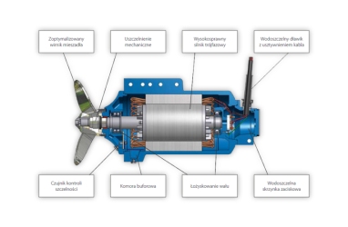
IMPELLER
- with 2 or 3 blades, self-cleaning
MOTOR
- 3-phase, 400 V, 50 Hz, protection IP68, insulation class F, bimetallic sensors installed in each phase, 10 m power cable, synthetic protective coating. Motor is cooled by the surrounding liquid.
SEALING
- Impeller shaft is sealed with two seals. The outward seal (liquid side) is a mechanical face seal acting independently of the rotation direction; very high durability, made of silicon carbide or tungsten; on the motor side the impeller shaft is sealed by a lip seal.
BUFFERING CHAMBER
- It protects the motor against moisture from possible leakages.
GUIDE VANES (only for impeller: 590 mm)
- It is a cylindrical tube in which the impeller runs. When this part is used, the stream range and capacities are improved. Made of stainless steel.
LEAKAGE DETECTION
- The mixer is equipped with an electronic leakage detection system. It indicates the presence of water in the buffering chamber.
Impeller blades:
- S type: epoxyde - composite
- SG type: steel 1.4301
- RHRS type: steel 1.4306
Motor body:
- cast iron Zl 250
Impeller shaft:
- stainless steel
Mechanical seal:
- SiC / SiC or SiC / Co
Other seals:
- fluoric elastomer (FKM)
crew joints:
- steel 1.4301 (1.4306)
Kierownica:
- steel 1.4301
STRUCTURE
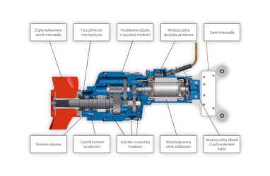
IMPELLER
- 2-blade, self-cleaning
MOTOR
- 3-phase, 400 V, 50 Hz, protection IP68, insulation class F, bimetallic sensors installed in each phase, 10 m power cable. Motor is cooled by the surrounding liquid. Synthetic protective coating.
REDUCTION GEAR
- 2 or 3 stage, high-durability helical reducer, with cast iron body, lubrication with synthetic oil, output shaft and external joints made of stainless steel, synthetic protection coating.
SEALING
- Impeller shaft is sealed with two seals. The outward seal (liquid side) is a mechanical face seal acting independently of the rotation direction; very high durability, made of silicon carbide; on the gearbox side the impeller shaft is sealed using a lip seal.
OIL CHAMBER
- Filled with synthetic oil. This is an additional protection of the gear against moisture and any leaks.
GUIDE VANES (only impellers: 480, 650, 800 mm)
- It is a cylindrical tube in which the impeller runs. When this part is used, the stream range and capacities are improved. Made of stainless steel.
LEAKAGE DETECTION
- The mixer is equipped with an electronic leakage detection system. It registers the presence of water in the oil chamber.
Impeller blades:
- Epidian epoxy resin + glass fiber (laminate)
Propeller hub:
- steel 1.4021 (2H13)
Motor body:
- cast iron Zl 250
Gearbox body:
- cast iron Zl 250
Impeller shaft:
- steel 1.4028 (3H13)
Mechanical seal:
- SiC / SiC
Other seals:
- fluoric elastomer (FKM)
Screw joints:
- steel 1.4301
Guide vanes:
- steel 1.4301
On the base of this information you can make your general design and select REDOR mixers equipped with optional leakage sensor or control unit. Please note, that the mixer in standard version is equipped only with temperature sensor installed in motor winding with external thermal contact.
Note: Different designs of mixers with and without leakage sensors. If you order mistakenly a mixer without sensor, the sensor can not be installed any more.
Leakage sensor indicates any water or sewage in the mixer interior. The FKS type control set connected to the sensor and installed in a hermetic casing is responsible for the winding contact status and leakage sensor control. The FKS control set is not responsible for ON/OFF motor control. It needs supply voltage of 230V and this supply voltage may not be connected directly from motor supply voltage. When the 230V voltage is on and the sensor do not indicate any failure to the mixer indication and control system, a relay signal is sent - contact closed. Otherwise, the contact status changes to „opened”. The set comprises indication lamps „mixer ready” but no mixer operation is indicated. The set is an integral part of a mixer with leakage sensor.
On special request, REDOR can deliver FK type control sets. They are responsible for the ON/OFF mixer control. The FK set is equipped with a main switch, start and stop button, fuses, contactors, additional thermal relay - selected depending on mixer motor size. The FK control set provides the functions: „remote/local” control switching, mixer operation status indication, „remote/local” status indication using relay contacts and status indication using indication lamps.
If you are interested in mixers equipped with leakage sensors or control set, we can send you detailed information about the connection and operation of such mixers.
REDOR supplies its sets in hermetic casings to be installed near the mixer (at the end of the mixer motor cable). Installation of the control sets in larger distances is not recommended because of possible interferences (stray currents, interferences from inverters etc.). In case of other installation requirements please contact us.
The control sets are installed in plastic boxes with transparent covers for interior operation, protection IP 65. The original sets include cable glands for mixer motor cable, system supply and control wires.
The following components are not included: brackets, roofs, installation bolts, cable glands for cables and wires to be supplied by the customer. We can supply these parts at special request.
The customer is responsible for the installation of the control sets in the object. REDOR can carry out these installation works as well as other electric and installation operation when specially requested.
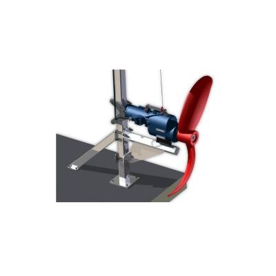
The single-column rotary supporting structure is equipped with slide bearing the mixer. The slide can move on a single guide (column) with square cross section form. The guide is installed at the bottom or wall of the tank and upper holder and can rotate together with the mixer in the range of ±60°. This way, the stream movement can be controlled in the required direction. During the operation, the mixer is supported by a bracket.
In the basic version, the mixer is suspended on a crane rope (option 1). Here, a separate crane for each mixer must be installed.
Mixer with chain (option 2) fixed to the supporting structure, with additional rope for mixer removal using crane is also available. This way, the mixer can be removed from the crane pocket or foot and used for operation of other mixers. This variant is not recommended because the crane must be transported on treatment plant platforms (inconvenience).
All structure components are made of stainless or constructional galvanized steel. Due to price differences between these versions, exact agreement with the manufacturer on the materials for the individual supporting structure components is necessary (see supporting structure selection chart).
Supporting structure, standard scope of delivery:
- Upper guide holder - 1 x
- Guide, length to 6 m – 1 x
- Mixer bracket – 1 x
- Guide base - 1 x
- Slide - 1 x
- Bolt set for guide holder and base assembling
- Jib crane in ceiling (X version) or pocket (Y version), assembling bolt set.
Guide middle holder is used only for guides with a length exceeding 6 m.
The single-column fix supporting structure is equipped with slide bearing the mixer. The slide can move on a single guide (column) with square cross section form.. The guide is installed to the tank bottom and upper holder. During the operation, the mixer is supported by a bracket. The mixer positioning direction is fixed at the supporting structure assembling and no adjustment during the operation is possible. This structure is applicable for heavy slow-speed mixers.
In the basic version, the mixer is suspended on a crane rope (option 1). Here, a separate crane for each mixer must be installed.
Mixer with chain (option 2) fixed to the supporting structure, with additional rope for mixer removal using crane is also available. This way, the mixer can be removed from the crane pocket or foot and used for operation of other mixers. This variant is not recommended because the crane must be transported on treatment plant platforms (inconvenience).
All structure components are made of stainless or constructional galvanized steel. Due to price differences between these versions, exact agreement with the manufacturer on the materials for the individual supporting structure components is necessary (see supporting structure selection chart).
Supporting structure, standard scope of delivery:
- Upper guide holder - 1 x
- Guide, length to 6 m – 1 x
- Mixer bracket – 1 x
- Guide base - 1 x
- Slide - 1 x
- Bolt set for guide holder and base assembling
- Jib crane in ceiling (X version) or pocket (Y version), assembling bolt set.
The double-column supporting structure is equipped with slide bearing the mixer. The slide can move on two guides (columns) with square cross section form. The guides are installed to the tank bottom and platform. Thanks to the application of two guides, safe assembling of heavy slow-speed mixers is possible.
In the basic version, the mixer is suspended on a crane rope (option 1). Here, a separate crane for each mixer must be installed.
Mixer with chain (option 2) fixed to the supporting structure, with additional rope for mixer removal using crane is also available. This way, the mixer can be removed from the crane pocket or foot and used for operation of other mixers. This variant is not recommended because the crane must be transported on treatment plant platforms (inconvenience).
All structure components are made of stainless or constructional galvanized steel. Due to price differences between these versions, exact agreement with the manufacturer on the materials for the individual supporting structure components is necessary (see supporting structure selection chart).
Supporting structure, standard scope of delivery:
- Upper holder (console) - 1 x
- Guide, length to 6 m – 2 x
- Safety cross bar – 1 x
- Guide base - 2 x
- Slide - 1 x
- Bolt set for guide holder and base assembling
- Jib crane in ceiling (X version) or pocket (Y version), assembling bolt set.